Page 5
(a)
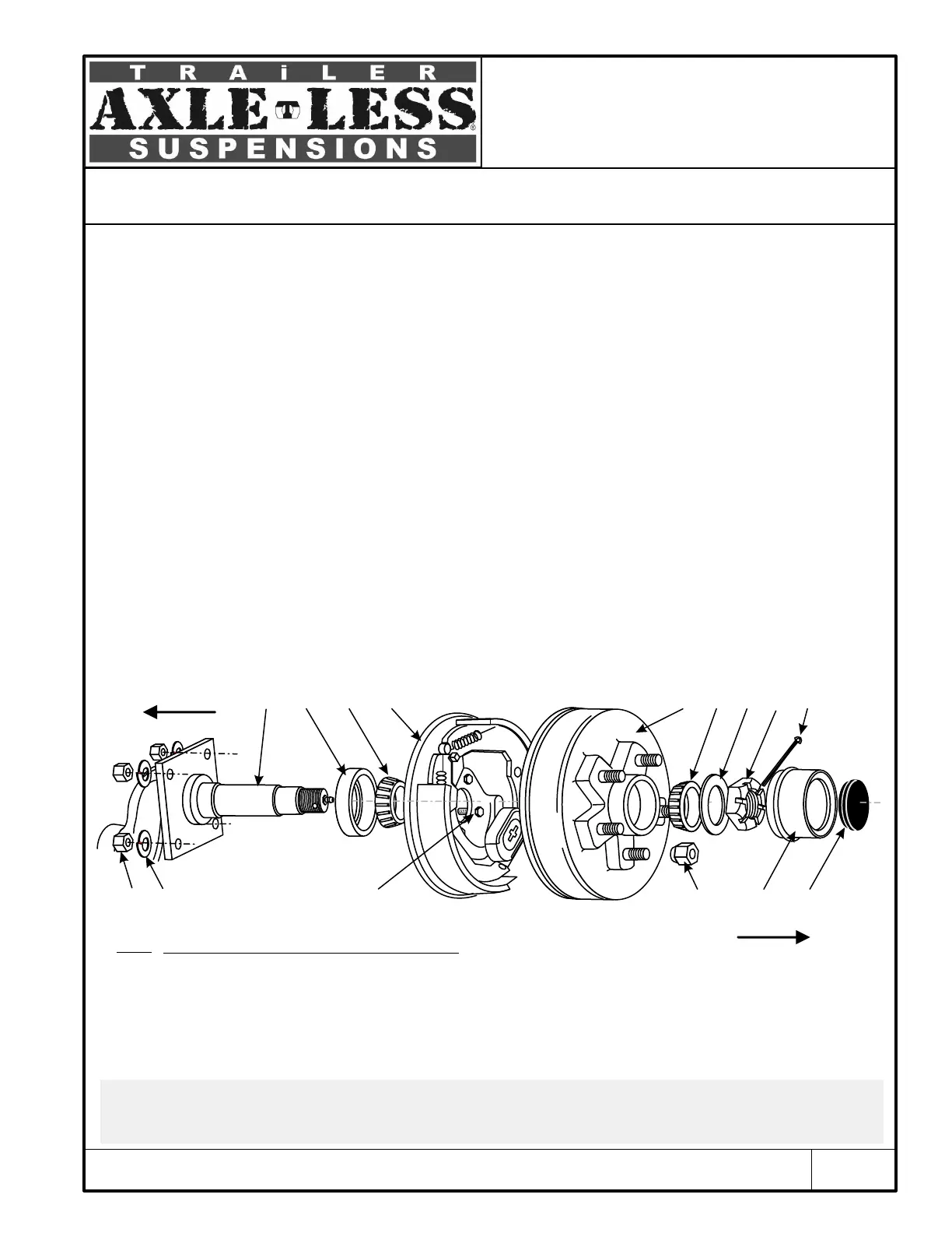
Installation of Hubs with Electric Brakes
(a) Parts of this document regarding the installation and maintenance of hubs and brakes are applicable ONLY if hubs and brakes are supplied by Timbren Industries Inc.
(b) Use a high temperature automotive type wheel bearing grease. We recommend using Lithium complex type products with NLGI consistency of 2, with additives for
EP (extreme pressure), corrosion and oxidation, dropping point of 419° F (min.) (or 215° C), with minimum viscosity index of 80.
(c) Always use NEW cotter pins (8).
Inboard
Outboard
Identify the left hand side (or L) and the right hand side (or R) brake (3A). You should be able to find either a
label inside each brake assembly or a note stamped on the body of the brake itself for the purpose of
identification. Install each brake to the backing plate of spindle arm at its corresponding side. The orientation
of brake is important: the magnet inside the assembly must be towards the bottom (the slack adjustor then,
will be at the bottom, brake shoe with shorter brake lining be at the front and the wires on the top).
Two wires on the inside of the backing plate must be connected to a brake controller which might be on either
the trailer or the tow vehicle (not supplied).
(b)
Grease inner and the outer bearings ((2A)&(2B)) . Insert inner bearing (2A) in its housing on the inboard side of
hub (3A) . Insert the grease seal (4) on top of the bearing and make sure it is fully seated. Turn hub around, lift
it and place it on the spindle (1) and slide it over into place. Position inner hub against the flange. Place five
7/16” lockwashers (#5) and five 7/16” UNF nuts (6) to mount each brake. Apply 50-55 ft.lbs (68-75 N.m) of
torque to each nut.
Position outer hub (3B) and insert outer bearing (2B). Put washer (7) and castle nut (8) onto spindle. Tighten nut
(8). Gently loosen it approximately 1/8 of a turn. Insert cotter pin (9) through castle nut and spindle hole and
then bend the end around the spindle with a screw driver or plyers. Put the grease cap (10) and rubber plug
(11) on.
Typical 5 Bolt Hub Assembly with Electric Brake
Fig. 2
1 4 3A
2A
3B
2B 7
8
10
13
11
9
5
6
TIMBREN INDUSTRIES INC. - 1-800-263-3113 - sales@timbren.com
12
Typical Installation


 To Previous Page
 Loading...