TROUBLESHOOTING
Should the relay fail to operate properly, check that all
three voltages are present and are of the correct level.
Check all fuses and verify that all wiring connections are
correct. Should problems persist, contact the factory for
assistance.
TYPICAL APPLICATION
WARRANTY
The Model 253 Reverse Phase Relay is covered by
Time Mark Corporation’s exclusive 5-Year
Unconditional Warranty. Should this device fail, for
any reason, within five years from the date of purchase,
we will repair or replace it. Contact the Time Mark
Sales department, Monday through Friday; 8 a.m. to 5
p.m., CST, for further details.
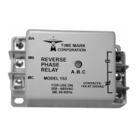
MODEL 253
Reverse Phase Relay
READ ALL INSTRUCTIONS BEFORE INSTALLING, OPERATING OR SERVICING THIS DEVICE.
KEEP THIS DATA SHEET FOR FUTURE REFERENCE.
GENERAL SAFETY
POTENTIALLY HAZARDOUS VOLTAGES ARE PRESENT AT THE TERMINALS OF THE MODEL 253.
ALL ELECTRICAL POWER SHOULD BE REMOVED WHEN CONNECTING OR DISCONNECTING WIRING.
THIS DEVICE SHOULD BE INSTALLED AND SERVICED BY QUALIFIED PERSONNEL.
Installation Instructions
TIME MARK is a division of
Telephone: Main - (918) 438-1220
Sales - (800) 862-2875
Fax: (918) 437-7584
E-mail: sales@time-mark.com
Internet: http://www.time-mark.com
Doc No. 87A113 12/00
© 2000 TIME MARK CORPORATION
11440 East Pine Street
Tulsa, Oklahoma 74116
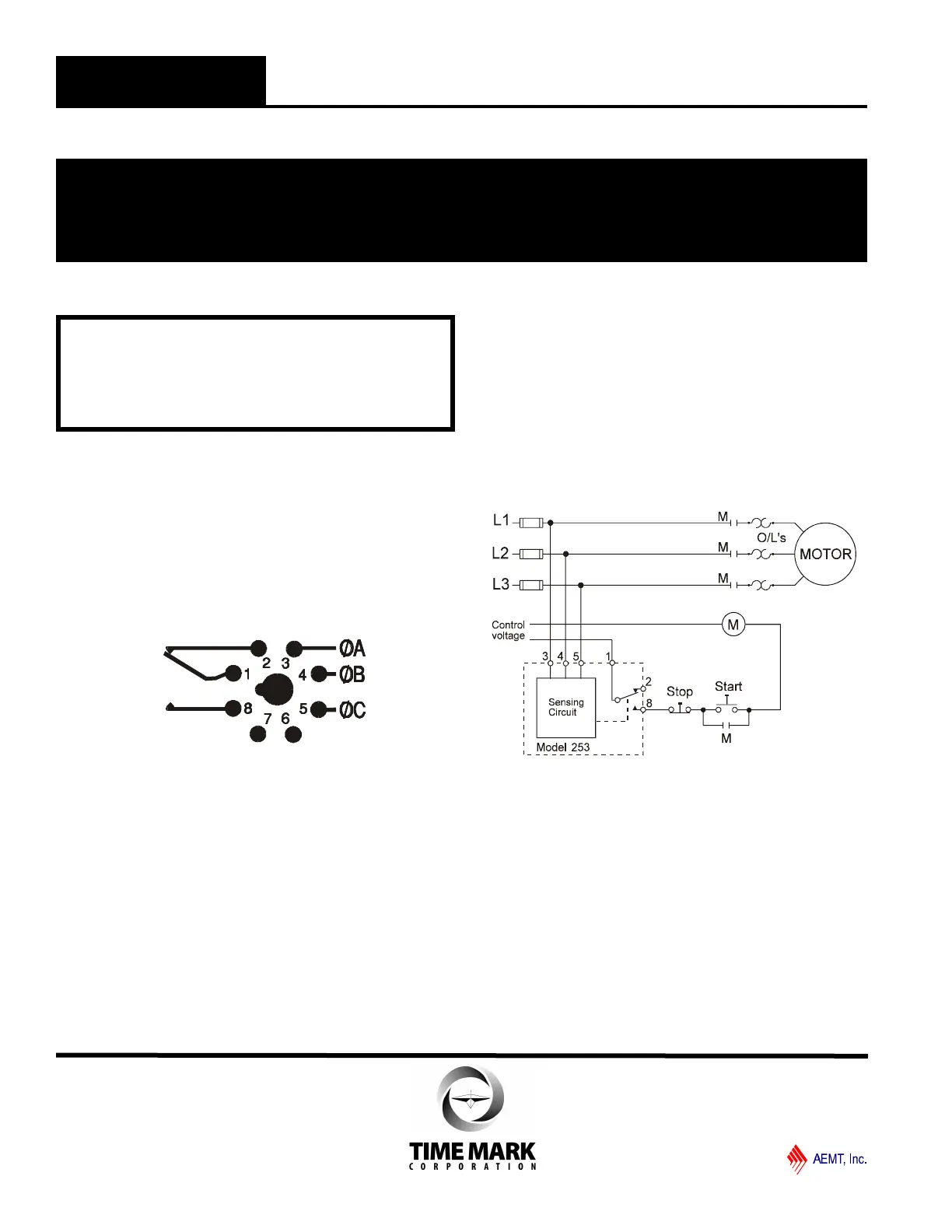
Shows No Power Applied
INSTALLATION
Refer to the Pin Drawing below, and on the case of the Model
253. The contacts are shown in the tripped condition.
Connect wiring to the socket as shown (an 8-pin socket, rated
for at least 480 VAC is required).
Refer to the Application Drawing for additional information.
PIN DRAWING
If the relay contacts do not transfer when power is applied
(indicator not lit), check that all three voltages are correct. If
power is present and of the correct voltage, remove power,
then reverse two of the three phase connections at the
socket.
Re-apply power. The contacts should transfer to the normal
condition (pins 1 and 8 closed; indicator lit). There are no
calibrations or adjustments required.
NOTE: When installing the Model 253 monitor in areas of high
humidity or contamination, it is recommended that the base area and
all exposed metal parts of the socket be coated liberally with a good
quality silicon grease, such as Dow Corning DC-4 or DC-4X. Insert
the unit into the socket and wipe off excess grease around the base.
This will prevent the entrance of moisture and other contaminates
into the base and socket areas.
WARNING
IN APPLICATIONS WHERE VOLTAGES IN EXCESS OF
300 VAC ARE TO BE MONITORED, BE CERTAIN TO USE
THE TIME MARK MODEL 51X120 8-PIN SOCKET, OR AN
EQUIVALENT UL APPROVED 600 VAC RATED SOCKET.
 Loading...