Slowly rotate the adjustment control in a counter-clockwise
direction, just until the green (NORM) indicator illuminates.
At this point, the Model 258 is the most sensitive to irregular
power line conditions. If nuisance tripping occurs, turn the
control slightly farther counter-clockwise.
A more accurate setting will require the use of a 3-phase
variac to lower the voltage to an exact measurable setting.
Time Mark also offers a factory set version of all models and
voltage ranges, for only a small additional charge.
TROUBLESHOOTING
Should the Model 258 Monitor fail to operate properly, check
that all three voltages are present, and are of the correct
voltage level and phase rotation (a Model 108A or 108B
Phase Sequence Detector should be used to verify phase
rotation). Check all fuses and verify that all wiring connections
are correct. If problems persist, contact your local Time Mark
Distributor, or the factory for assistance (Monday-Friday, 8 a.
m. to 5 p.m. CST).
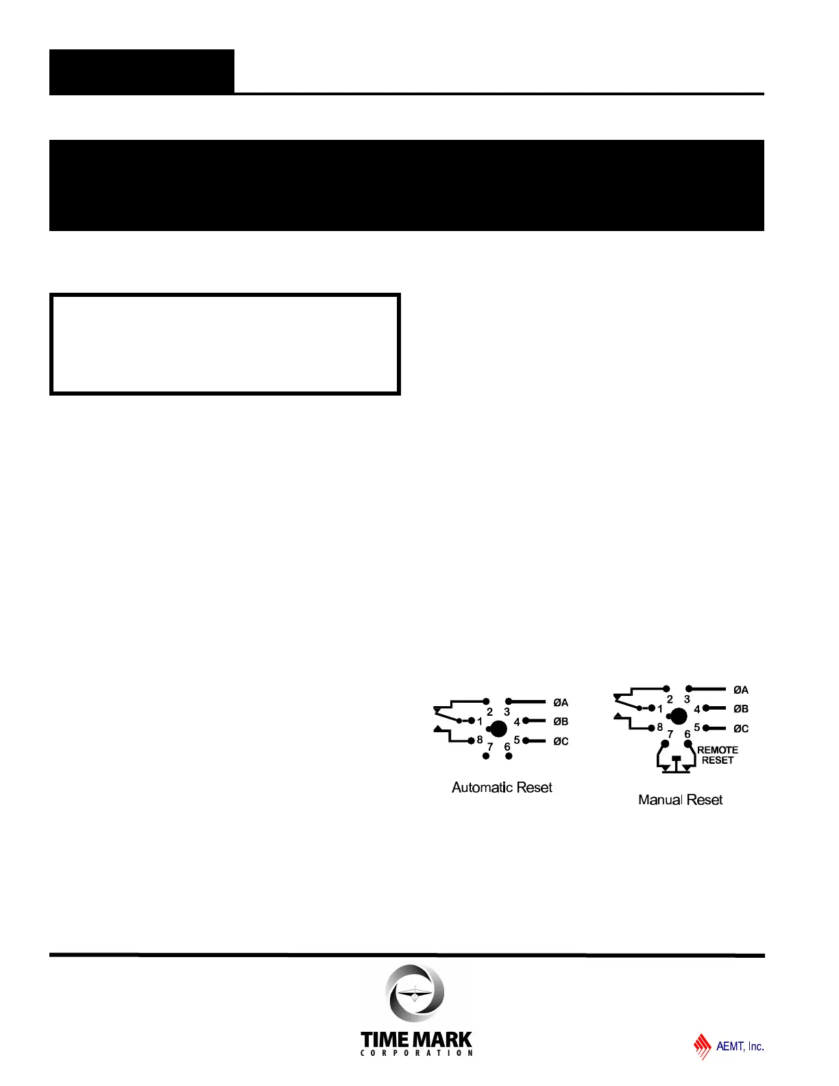
MANUAL RESET VERSIONS
IF YOU DO NOT WISH TO USE A NORMALLY CLOSED
EXTERNAL RESET SWITCH ON THE MANUAL RESET
VERSION, YOU MUST JUMPER PINS 6 AND 7. Refer to
the Manual Reset 8-pin diagram.
WARRANTY
The Model 258 3-Phase Monitor is warranted to be free from
defects in materials and workmanship, and is covered by our
exclusive 5-year Unconditional Warranty. If this device fails
to operate, for any reason, we will repair or replace it free, for
five years from the date of purchase. Contact the Time Mark
Sales department for further details.
INSTALLATION
Mount the 8-pin socket in a suitable enclosure. A NEMA-1
rated enclosure, designed for socket-mounted relays is
available from Time Mark Corporation.
Connect 3-phase power to terminals 3, 4, and 5 on the
socket. Phase rotation should be verified using a Time Mark
Model 108A or 108B Phase Sequence Detector.
Connect the load control wiring to the appropriate terminals
on the socket:
For motor control applications; use terminals 1 and 8.
For phase loss alarm applications; use terminals 1 and 2.
Insert the Model 258 into the socket and apply power. If the
contact does not transfer (green light ON), check that all
phases are present, and of the correct voltage. If power is
correct, rotate the level adjustment counter-clockwise.
If the contact still does not transfer, remove power and
reverse any two of the three phase wires at the socket (phase
rotation is reversed). Re-apply power. The contact should
transfer to provide a signal path between pins 1 and 8.
NOTE: When installing the Model 258 monitor in areas of high
humidity or contamination, it is recommended that the base area
and all exposed metal parts of the socket be coated liberally with
a good quality silicon grease, such as Dow Corning DC-4 or DC-
4X. Insert the unit into the socket and wipe off excess grease
around the base. This will prevent the entrance of moisture and
other contaminates into the base and socket areas.
ADJUSTMENT SETTINGS
The following procedure will allow the Model 258 to be
adjusted to achieve a trip point just below the nominal phase-
to-phase voltage, where the unit is applied.
Rotate the adjustment control fully clockwise, or until the red
(TRIP) indicator illuminates.
WARNING
IN APPLICATIONS WHERE VOLTAGES IN EXCESS OF
300 VAC ARE TO BE MONITORED, BE CERTAIN TO USE
THE TIME MARK MODEL 51X120 8-PIN SOCKET, OR AN
EQUIVALENT UL APPROVED 600 VAC RATED SOCKET.
MODEL 258
3-Phase Monitor
READ ALL INSTRUCTIONS BEFORE INSTALLING, OPERATING OR SERVICING THIS DEVICE.
KEEP THIS DATA SHEET FOR FUTURE REFERENCE.
GENERAL SAFETY
POTENTIALLY HAZARDOUS VOLTAGES ARE PRESENT AT THE TERMINALS OF THE MODEL 258.
ALL ELECTRICAL POWER SHOULD BE REMOVED WHEN CONNECTING OR DISCONNECTING WIRING.
THIS DEVICE SHOULD BE INSTALLED AND SERVICED BY QUALIFIED PERSONNEL.
Installation Instructions
TIME MARK is a division of
Telephone: Main - (918) 438-1220
Sales - (800) 862-2875
Fax: (918) 437-7584
E-mail: sales@time-mark.com
Internet: http://www.time-mark.com
Doc No. 87A123 12/00
© 2000 TIME MARK CORPORATION
11440 East Pine Street
Tulsa, Oklahoma 74116
 Loading...