TYPICAL APPLICATION
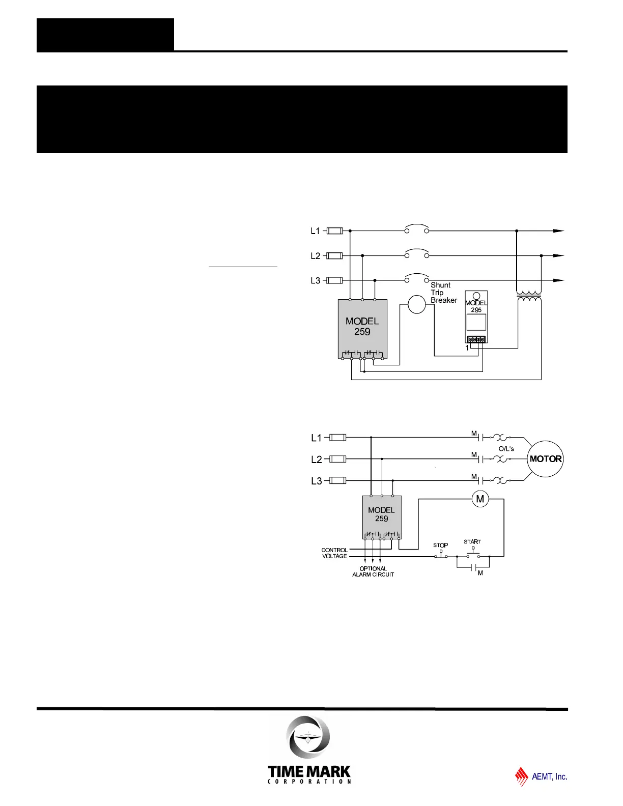
Individual Motor Protection
INSTALLATION
Connect the 3-phase wiring to the terminals marked
L1, L2, L3.
Connect the control wiring to the terminals with the
contact markings (refer to the diagram on the unit). The
markings shown on the unit are the failed condition of
the contacts.
Apply power. If the contacts do not transfer (FAILURE
INDICATOR=Off), check that all three phases are
present and of the correct voltage. If all phases are
correct, rotate the VOLTAGE LEVEL adjustment
counter-clockwise to the MIN position.
If the contacts still do not transfer, remove power from
the unit. Reverse two of the three input wires and re-
apply power. The contacts should transfer to the
normal condition (normally-open contacts closed,
FAILURE INDICATOR=Off).
Note: Upon initial power up with proper voltage and phase
sequence it will take about 12 seconds before the trip led
will go out and the contacts will transfer to the normal state.
When making voltage level adjustments after the unit is
tripped the above will apply.
ADJUSTMENT
Note: During adjustment you may want to install a jumper
across the control contacts to prevent cycling the load on
and off.
Set the TRIP DELAY to 1 second. Rotate the
VOLTAGE LEVEL adjustment slowly clockwise, until
the contacts transfer to the failed condition (FAILURE
INDICATOR=On). Slowly turn the adjustment
counterclockwise until the contacts reset to the normal
condition (FAILURE INDICATOR=Off).
Remove the jumper, if installed.
This setting will be correct for most applications. The
trip delay will prevent most nuisance tripping; however,
if nuisance tripping does occur, turn the VOLTAGE
LEVEL slightly farther counter-clockwise.
In making adjustments to eliminate nuisance tripping,
the VOLTAGE LEVEL adjustment should be rotated in
very small increments until the true nuisance trips are
eliminated. Adjust the TRIP DELAY setting, and RE-
START DELAY as required for the application.
WARRANTY
The Model 259 3-Phase Monitor is covered by Time
Mark Corporation’s exclusive 5-Year Unconditional
Warranty. Should this device fail, for any reason,
within five years from the date of purchase, we will
repair or replace it free. Contact the Time Mark Sales
department, Monday through Friday; 8 a.m. to 5 p.m.,
CST, for further details.
TYPICAL APPLICATION
Shunt Trip Breaker Operation
MODEL 259
3-Phase Monitor
READ ALL INSTRUCTIONS BEFORE INSTALLING, OPERATING OR SERVICING THIS DEVICE.
KEEP THIS DATA SHEET FOR FUTURE REFERENCE.
GENERAL SAFETY
POTENTIALLY HAZARDOUS VOLTAGES ARE PRESENT AT THE TERMINALS OF THE MODEL 259.
ALL ELECTRICAL POWER SHOULD BE REMOVED WHEN CONNECTING OR DISCONNECTING WIRING.
THIS DEVICE SHOULD BE INSTALLED AND SERVICED BY QUALIFIED PERSONNEL.
Installation Instructions
TIME MARK is a division of
Telephone: Main - (918) 438-1220
Sales - (800) 862-2875
Fax: (918) 437-7584
E-mail: sales@time-mark.com
Internet: http://www.time-mark.com
Doc No. 87A116 12/00
© 2000 TIME MARK CORPORATION
11440 East Pine Street
Tulsa, Oklahoma 74116
 Loading...