INSTALLATION
Connect the 3-phase wires to the terminals marked A, B
and C. Turn both controls fully counter-clockwise.
Connect the control wires to the terminals with the relay
contact markings. NOTE: The contact markings on the
unit are the TRIPPED condition of the contacts.
Apply power. If the contacts do not transfer when power is
applied (NORMAL indicator on), check that all three
phases are present, and of the correct voltage. If all
phases are correct, rotate the VOLTAGE adjustment
counter-clockwise, to the low position. If the contacts still
do not transfer, remove power from the unit. Reverse any
two of the three input wires, and re-apply power. The
contacts should transfer to the normal condition (normally-
open contact closed, NORMAL indicator ON).
ADJUSTMENT
NOTE: During adjustment, you may want to install a
jumper across the control contacts, to prevent cycling the
load on and off.
Set the trip delay to .2 seconds.
Rotate the VOLTAGE adjustment slowly clockwise until the
contacts transfer to the failed condition (TRIPPED indicator
lit).
Slowly turn the VOLTAGE adjustment counter-clockwise,
until the contacts reset to the normal condition (NORMAL
indicator on).
WARNING
The Model 264 is not to be used in applications
where voltages to be monitored or switched
will exceed voltage specifications for the
particular unit. See ‘Adjustment Range’ in the
Specifications table on the reverse side of this
data sheet.
MODEL 264
3-Phase Monitor
READ ALL INSTRUCTIONS BEFORE INSTALLING, OPERATING OR SERVICING THIS DEVICE.
KEEP THIS DATA SHEET FOR FUTURE REFERENCE.
GENERAL SAFETY
POTENTIALLY HAZARDOUS VOLTAGES ARE PRESENT AT THE TERMINALS OF THE MODEL 264.
ALL ELECTRICAL POWER SHOULD BE REMOVED WHEN CONNECTING OR DISCONNECTING WIRING.
THIS DEVICE SHOULD BE INSTALLED AND SERVICED BY QUALIFIED PERSONNEL.
Installation Instructions
If you installed a jumper across the control contacts to
prevent load cycling, remove it now.
Set the SECONDS adjustment to the desired amount of
trip delay. ThIs trip delay will prevent most nuisance
tripping; however, if nuisance tripping does occur, turn the
VOLTAGE adjustment slightly farther, counter-clockwise.
In making adjustments to eliminate nuisance tripping,
the VOLTAGE adjustment should be rotated in very
small increments, until the true nuisance trips are
eliminated.
WARRANTY
The Model 264 3-Phase Monitor is covered by Time Mark
Corporation’s exclusive 5-Year Unconditional Warranty.
Should this device fail, for any reason, within five years
from the date of purchase, we will repair or replace it free.
Contact the Time Mark Sales department, Monday through
Friday; 8 a.m. to 5 p.m., CST, for further details.
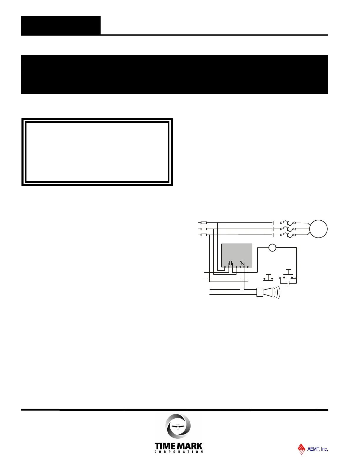
TYPICAL APPLICATION
A B C
START
STOP
M
M
M
M
MOTOR
M
L1
L2
L3
MODEL
264
CONTROL
CIRCUIT
ALARM
CIRCUIT
TIME MARK is a division of
Telephone: Main - (918) 438-1220
Sales - (800) 862-2875
Fax: (918) 437-7584
E-mail: sales@time-mark.com
Internet: http://www.time-mark.com
Doc No. 87A127 12/00
© 2000 TIME MARK CORPORATION
11440 East Pine Street
Tulsa, Oklahoma 74116
Shown De-Energized
 Loading...