Set the TRIP DELAY adjustment to the desired amount of
delay to prevent nuisance trips.
These adjustment settings will be correct for most
applications. Should nuisance trips occur, even with the
TRIP DELAY set, turn the VOLTAGE ADJUST pot slightly
farther counter-clockwise. Any adjustments should be
made in very small increments.
WARRANTY
The Model 2642 3-Phase Monitor is covered by Time
Mark Corporation’s exclusive 5-Year Unconditional
Warranty. Should this device fail, for any reason, within
five years from the date of purchase, we will repair or
replace it free. Contact the Time Mark Sales
department, Monday through Friday; 8 a.m. to 5 p.m.,
CST, for further details.
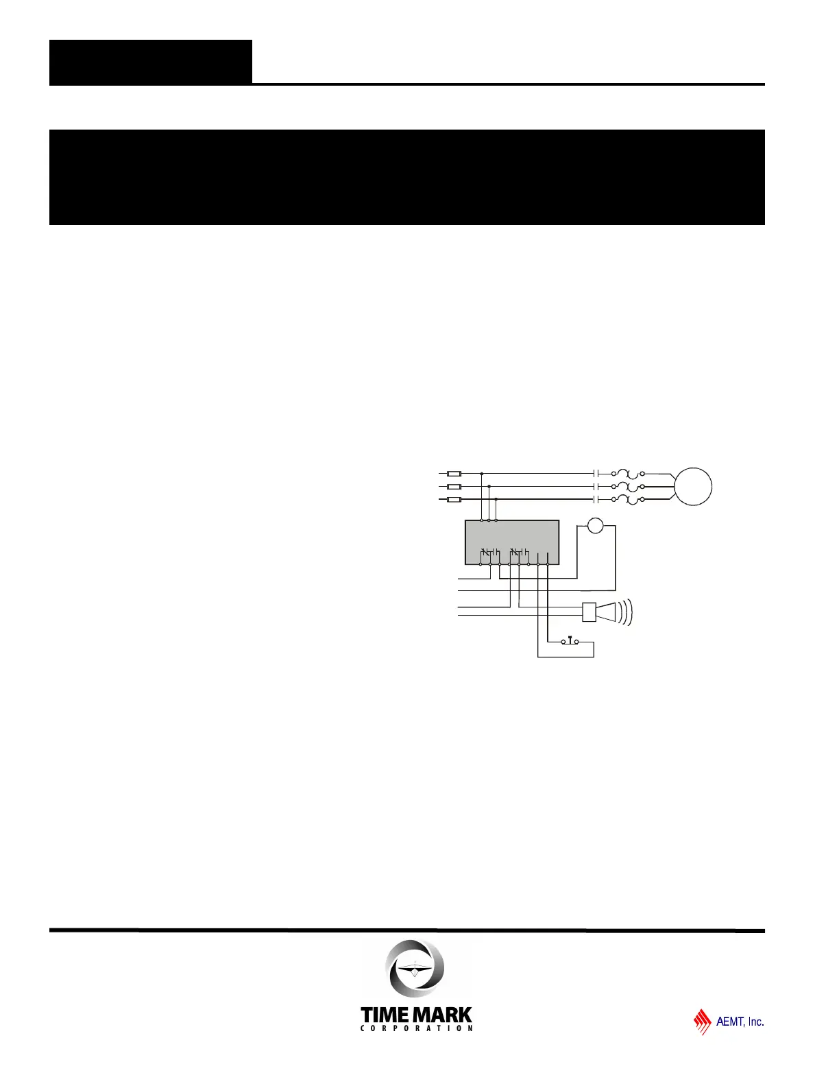
Alarm (optional)
M
M
Motor
M
L1
L2
L3
Control
Voltage
Alarm
Circuit
O/L
M
A BC
Model 2642
RESET
Manual Reset (omit for auto reset)
Shown with no power applied
MODEL 2642
3-Phase Monitor
READ ALL INSTRUCTIONS BEFORE INSTALLING, OPERATING OR SERVICING THIS DEVICE.
KEEP THIS DATA SHEET FOR FUTURE REFERENCE.
GENERAL SAFETY
POTENTIALLY HAZARDOUS VOLTAGES ARE PRESENT AT THE TERMINALS OF THE MODEL 2642.
ALL ELECTRICAL POWER SHOULD BE REMOVED WHEN CONNECTING OR DISCONNECTING WIRING.
THIS DEVICE SHOULD BE INSTALLED AND SERVICED BY QUALIFIED PERSONNEL.
Installation Instructions
INSTALLATION
Turn both adjustment control potentiometers fully counter-
clockwise.
Connect the 3-phase wires to the terminals marked A, B
and C.
Connect the control wires to one set of the terminals with
the relay contact markings. The contact markings on the
unit are the failed or tripped condition of the contacts. The
second set of output terminals can be used in an alarm
circuit or in the control circuit of a second load. Refer to
the TYPICAL APPLICATION drawing.
As provided, the Model 2642 has an Automatic Reset. If
you prefer a Manual Reset, install a normally-closed push
button across the terminals marked RESET. The Manual
Reset leads should be kept as short as possible.
Apply power. If the contacts do not transfer when power is
applied (TRIPPED indicator off; NORMAL indicator on),
check that all three phases are present and of the correct
voltage.
If all phases are correct, remove power from the unit,
reverse any two of the A, B or C terminal wires (phase
rotation is reversed), and re-apply power. The contacts
should then transfer.
ADJUSTMENT
NOTE: When adjusting the Model 2642 you may wish to
jumper the control circuit contacts (& disconnect the alarm
contacts, if used) to prevent the unit from cycling the load.
Rotate the VOLTAGE ADJUST pot clock-wise until the unit
trips (NORMAL indicator off, TRIP indicator on).
Slowly turn the VOLTAGE ADJUST pot counter-clockwise
until the unit resets (TRIP indicator off; NORMAL indicator
on).
Shows No Power Applied
TIME MARK is a division of
Telephone: Main - (918) 438-1220
Sales - (800) 862-2875
Fax: (918) 437-7584
E-mail: sales@time-mark.com
Internet: http://www.time-mark.com
Doc No. 87A169 12/00
© 2000 TIME MARK CORPORATION
11440 East Pine Street
Tulsa, Oklahoma 74116
TYPICAL APPLICATION
 Loading...