ADJUSTMENT PROCEDURE
Set UNDER VOLTAGE level: Rotate the UNDER
VOLTAGE adjustment pot clockwise, until the contacts
transfer (UNDER VOLTAGE LED-On). Slowly turn the
UNDER VOLTAGE adjustment counter-clockwise until the
contacts reset (UNDER VOLTAGE LED-Off).
Set OVER VOLTAGE level: Turn the OVER VOLTAGE
adjustment pot counter-clockwise, until the contacts
transfer (OVER VOLTAGE LED-On). Slowly turn the
OVER VOLTAGE adjustment pot clockwise until the
contacts reset (OVER VOLTAGE LED-Off).
Nuisance tripping: The settings achieved by these adjust-
ments (above), will be correct for most applications.
Should nuisance tripping occur, turn the OVER VOLTAGE
and the UNDER VOLTAGE adjustments slightly further,
widening the operating band.
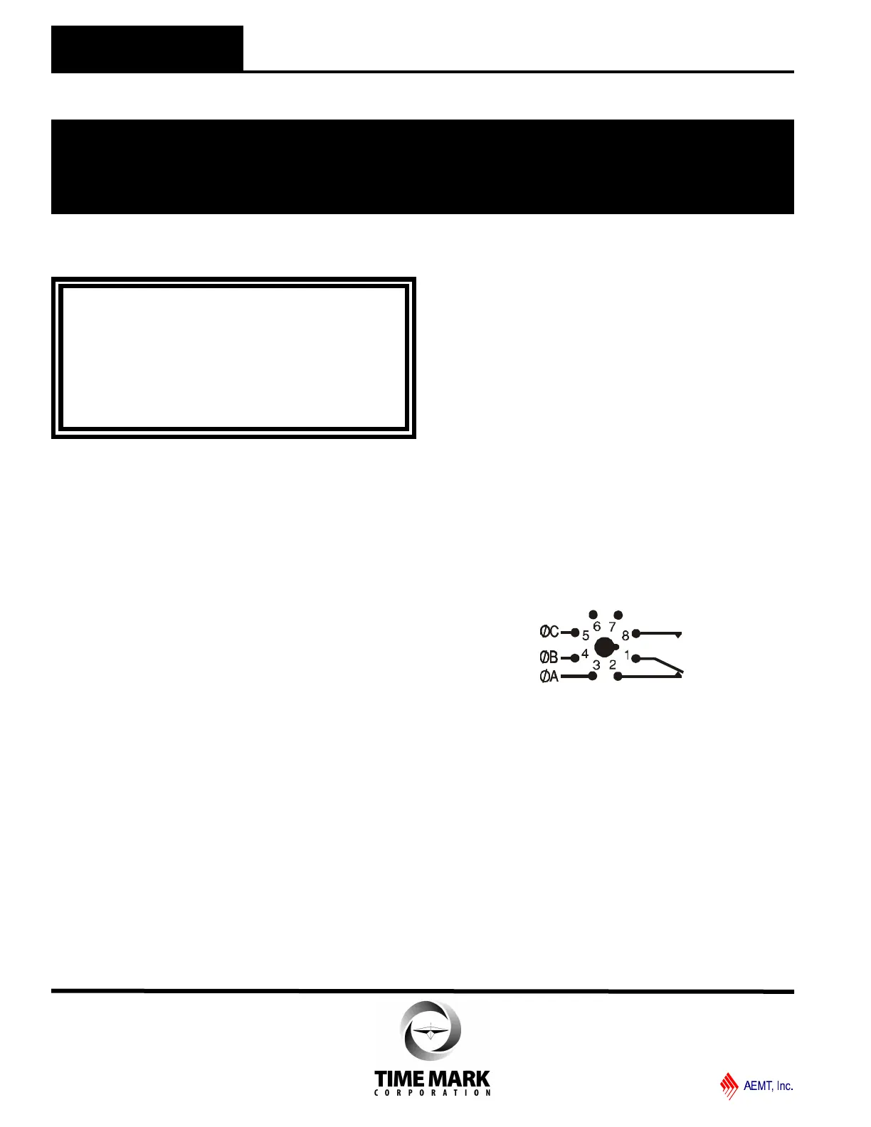
PIN DIAGRAM
TROUBLESHOOTING
Should the Model 246 3-Phase Monitor fail to operate,
check all connections. Verify that all three voltages are
present, and check all fuses. Should problems persist,
contact the factory for assistance.
WARRANTY
The Model 246 3-Phase Monitor is covered by Time
Mark Corporation’s exclusive 5-Year Unconditional
Warranty. Should this device fail, for any reason, within
five years from the date of purchase, we will repair or
replace it free. Contact the Time Mark Sales
department, Monday through Friday; 8 a.m. to 5 p.m.,
CST, for further details.
WARNING
The Model 246 is not to be used with input
voltages greater than those for which the unit was
designed.
140VAC for Model A246
280VAC for Model B246
INSTALLATION
Connect the input power to the 8-pin socket, following
the Model 246 pin diagram, pictured on the unit, and on
this data sheet. Insert the Model 246 into the socket
and apply power.
If the contacts do not transfer (both LEDs-off), check
that all three phases are present and of the correct
voltage. If power is correct, rotate the UNDER
VOLTAGE adjustment counter-clockwise, and the
OVER VOLTAGE adjustment clockwise, to widen the
operating band.
If the contacts still do not transfer, remove power and
reverse two of the three phase wires, at the socket
(phase rotation is reversed). Re-apply the power. The
contacts should transfer to provide a signal path
between pins 1 & 8 (both LEDs-off).
NOTE: When installing the Model 246 Monitor in
areas of high humidity or contamination, it is
recommended that the base area and all exposed metal
parts of the socket be coated liberally with a good
quality silicon grease, such as Dow Corning DC-4 or
DC-4X. Insert the unit into the socket and wipe off
excess grease around the base. This will prevent the
entrance of moisture and other contaminates into the
base and socket areas.
MODEL 246
3-Phase Monitor
READ ALL INSTRUCTIONS BEFORE INSTALLING, OPERATING OR SERVICING THIS DEVICE.
KEEP THIS DATA SHEET FOR FUTURE REFERENCE.
GENERAL SAFETY
POTENTIALLY HAZARDOUS VOLTAGES ARE PRESENT AT THE TERMINALS OF THE MODEL 246.
ALL ELECTRICAL POWER SHOULD BE REMOVED WHEN CONNECTING OR DISCONNECTING WIRING.
THIS DEVICE SHOULD BE INSTALLED AND SERVICED BY QUALIFIED PERSONNEL.
Installation Instructions
TIME MARK is a division of
Telephone: Main - (918) 438-1220
Sales - (800) 862-2875
Fax: (918) 437-7584
E-mail: sales@time-mark.com
Internet: http://www.time-mark.com
Doc No. 87A112 12/00
© 2000 TIME MARK CORPORATION
11440 East Pine Street
Tulsa, Oklahoma 74116
 Loading...