9.9 Adjusting the PK-900 4.0 MHz Oscillator
Note: The following only applies to the black & white FAX mode of
the PK-900 and does not apply to the Analog mode.
If you ever observe the received FAX from a Commercial station does
not display straight up and down the page, your 4.00 MHz oscillator
inside the PK-900 has probably drifted off frequency. If you have a
frequency counter with a high-impedance input, you may do the
following:
Step 1: Open the PK-900 by removing the 4 screws that hold the gray
top chassis in place and separate it from the bottom chassis.
Step 2: Reconnect the PK-900 to +13 VDC, then turn it on, and allow
it to warm-up for 30 minutes.
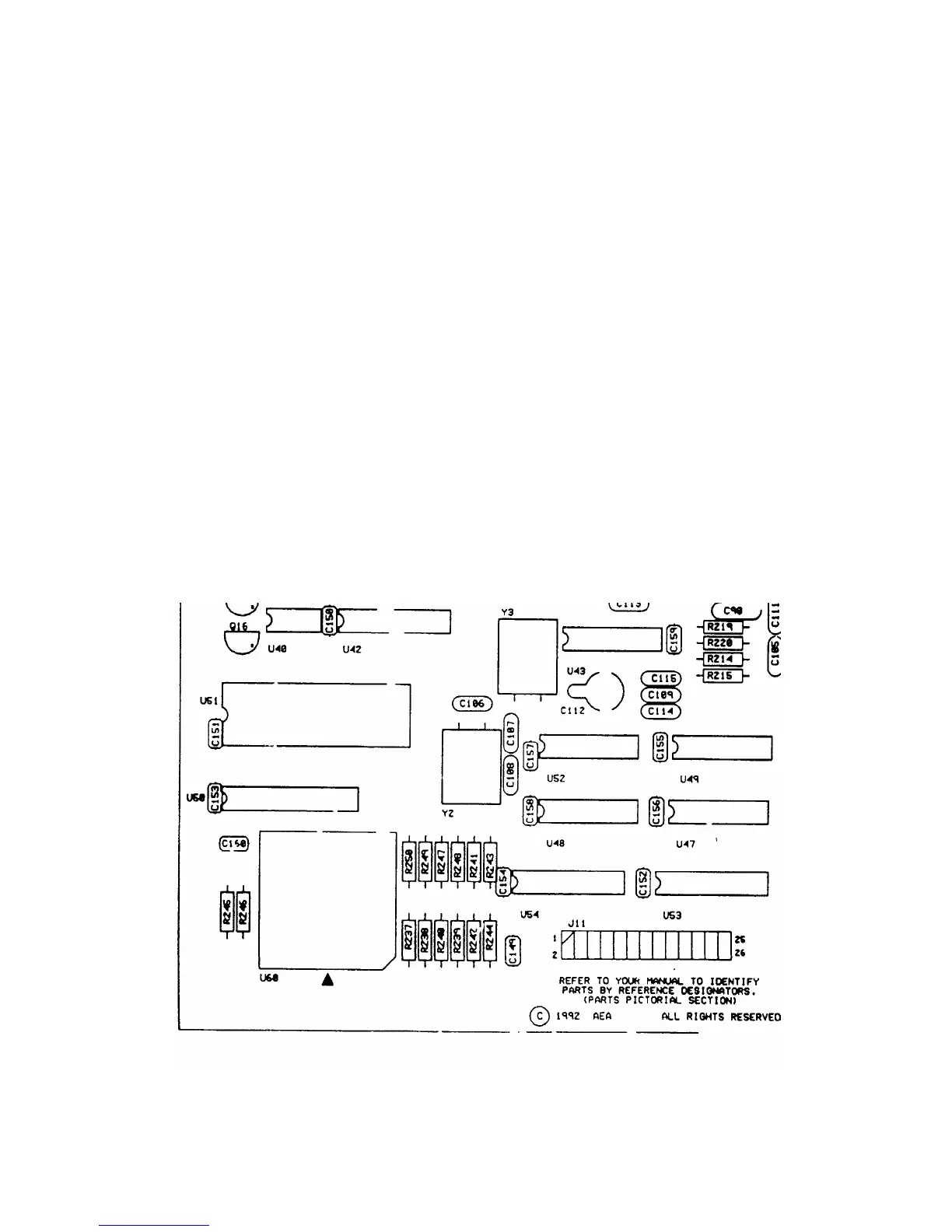
Step 3: With the help of Figure 2 below, locate the variable
capacitor C112 in the left-front quadrant of the PK-900 circuit
board. It is located near the U43 and Y3.
Step 4: Place the probe of the frequency counter on pin-16 of IC
U35, the Z8536 which will provide a strong square-wave clock signal.
Step 5: Adjust C112 until the counter reads 4.00000 MHz +/- 10 Hz.
Figure 2: PK-900 circuit board layout showing the location of C112
1/93 9-8