Do you have a question about the TissueLink Aquamantys System and is the answer not in the manual?
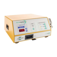
Overview of the electrosurgical generator and peristaltic pump system.
Details on bipolar RF power delivery and concurrent saline delivery.
Describes saline flow rate settings and the priming function.
Details major controls and indicators on the front panel.
Details further controls on the front panel.
Details rear panel identification plates and connectors.
Details output configuration, cooling, and display specifications.
Physical dimensions and weight of the pump generator.
Specifies ambient temperature, humidity, and air pressure limits.
Specifies EMC compliance and immunity tests.
Lists relevant safety and classification standards.
Details maximum output, RF output, and waveform specifications.
Lists power cords for different regions.
Details fuse types and ratings for the system.
Lists the main components of the pump generator.
Details the primary and secondary power supply circuits.
Details the RF generator PCB, voltage regulators, and microcontrollers.
Describes the display PCB connection and function.
Covers shock and burn hazards during servicing.
Includes static control, lead management, and duty cycle adherence.
Outlines manufacturer responsibilities for safety and performance.
Recommendations for periodic service intervals and procedures.
Details PE conductor and leakage current measurement procedures and limits.
Explains measurement of RF leakage current and activation method.
Describes how to verify RF output power accuracy.
Procedures for testing pump function and flow rate accuracy.
Instructions for obtaining an RMA number, cleaning, and shipping.
Initial checks for obvious problems.
Table for identifying and correcting specific malfunctions.
Guidance on handling unit alarms and error codes.
Describes error display during self-test and initial error handling.
Details error codes specific to MPU1.
Steps to open the unit for service.
Procedures for removing power supply, rear panel, and PCBs.
Details the one-year warranty terms for the product.
| Brand | TissueLink |
|---|---|
| Model | Aquamantys System |
| Category | Inverter |
| Language | English |