Do you have a question about the Titan Logix FINCH 5332 and is the answer not in the manual?
Provides information specific to the Titan Logix Corp. Finch 5332/5332E Level Monitor.
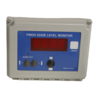
Explains the TD80 system, Finch 5332 internal and 5332E external displays.
Lists key features like enclosure types, input/output, reliability, and programming.
Details ideal and avoid mounting locations based on weather, sunlight, temperature, and wiring accessibility.
Shows dimensions for Finch 5332 and Finch 5332E models.
Describes mounting methods for Finch 5332 internal and 5332E external displays using brackets or bolts.
Illustrates jumper locations and I/O terminals for Finch 5332 internal display and external connections.
Explains how power is supplied to the TD80 Level Transmitter and level data is sent via SVbus.
Describes the function of the PTO switch for Monitor Mode and external acknowledge for alarms.
Details the use of the HH alarm relay for pump shutdown, its fail-safe operation, and wiring for open/closed circuits.
Explains the Fill alarm for desired level indication, its fail-safe operation, and the Horn Circuit OK LED.
Describes the Fail Alarm for system errors, its dry contact nature, and fail-safe operation for spill protection.
Advises on correct voltage supply (8-28VDC) and initial setup precautions for the Finch Display.
Describes the power-on sequence, transmitter and display self-diagnostics, and initial relay tests.
Outlines the process for calibrating the system using known fluid levels and front panel buttons.
Illustrates the transitions between Monitor, Display, Set Fill/Fall, and Off modes based on PTO and button inputs.
Explains the sleep mode where the display is off and how to exit it via buttons or PTO.
Describes showing current level and errors, returning to Off Mode, and conditions for 2 LO or Spill display.
Details displaying level, errors, and alarms, and entering other modes via PTO or buttons.
Explains adjusting Fill/Fall alarm levels using faceplate buttons and the effect of the Fill/Fall Jumper.
Describes using the 2 LO Disable Jumper to prevent "----" from appearing, with a note on accuracy.
Defines the operator-entered Fill/Fall level, its relay activation, and acknowledgement procedure.
Explains the HH Alarm level set 8" from the top, its use for pump shutdown, and acknowledgement.
Describes the Fail Alarm for system errors, loss of communication, or Spill Alarm, and its self-resetting nature.
Details the Spill Alarm level set near the top, its effect on the Fail Alarm, and reset conditions.
Explains the proprietary SVbus communication system, its range, and termination requirements.
Details the structure and meaning of data fields within the 'r' Frame used for level transmission.
Describes the 'L' Frame data packet sent by the Finch Display to the level transmitter during calibration mode.
Details the 'I' Frame, a calibration data packet sent by the transmitter to the Finch Display as a reply to an 'L' frame.
| Brand | Titan Logix |
|---|---|
| Model | FINCH 5332 |
| Category | Monitor |
| Language | English |