INSTALLATION
To facilitate installation, you will need a drill and various
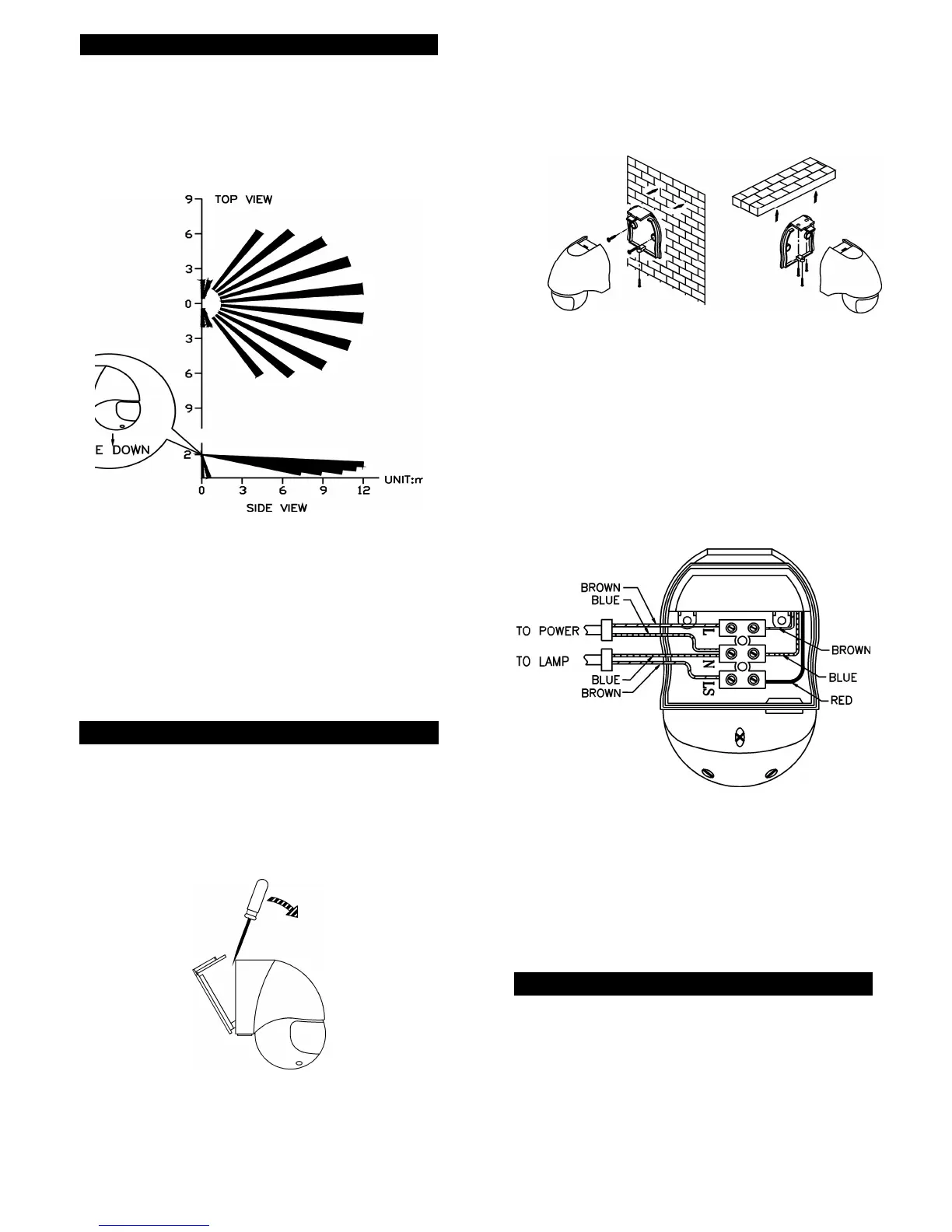
screwdrivers. Select a location for the unit based on
the coverage angles shown in FIGURE 3.
COVERAGE ANGLES
FIGURE 3
It is suggested that a wall switch is installed to control
the power supply to the sensor. This will allow the
sensor to be switched off if not required or for
maintenance purposes, and will allow use of the
manual override function.
WIRING INSTRUCTION
(1) Switch off the power source or wall switch.
(2) Unscrew one screw from the bottom housing. By
using a flat blade screwdriver to detach the base
cover from the unit. (FIGURE 4)
FIGURE 4
2
(3) Make use of the base cover as a template to mark
the position of two screw holes on the wall or on
the ceiling. Drill the wall and screw the base cover
onto the wall or ceiling using suitable plastic wall
plugs and screws provided (FIGURE 5 & 6).
Wall Mounting Ceiling Mounting
FIGURE 5 FIGURE 6
(4) Strip approximately 6-8mm insulating part of the
wires from the power cord. Before connection, run
the wires through the rubber seal provided.
Note: The power cord must meet H05RN-F, 1.0mm²
requirement.
(5) For POWER connection, connect the BROWN
wire (Live wire) to the terminal block “L” mark.
Connect the BLUE wire (Neutral wire) to the
terminal block “N” mark (FIGURE 7).
FIGURE 7
(6) For LAMP connection, connect the 'BLUE' wire to
the terminal block 'N' mark. Connect the
'BROWN' wire to the terminal block 'LS' mark.
(7) Fix the pre-wired terminal block to it’s mounting
boss firmly.
(8) Refit and screw the unit to the base cover. Ensure
the rubber seal is correctly seated.
SETTING THE LIGHTING SYSTEM
(1) TEST MODE
Turn the LITE control and the TIME control fully
counter clockwise – the TEST position:
3
 Loading...