ECM Overview and Setup
DDC Control - Air Balance
If the DDC Controller signal is already installed, air
balance can be achieved using the DDC Controller
software tools. Please notice that a control signal less than
0.2Vdc may put the interface board into manual override.
Avoid setting the DDC signal to less than 0.2Vdc.
Cycle power ON/OFF for faster lockout removal.
Manual Air Balance
The interface board can be manually adjusted before the
DDC Controller signal is available. The balancer’s manual
adjustment has authority until automation is connected.
Air Balancer
1. Use Adjust to set the air flow. This adjustment will have
authority for at least 15 minutes.
2. Read the flashing green light and record the flow index
on the air balance report.
DDC Integrator
1. Set the Signal to 0Vdc to invoke manual override.
2. Record the RPM on the air balance report.
3. Enter the flow index the air balancer entered on the air
balance report.
4. Observe the RPM is at or near the RPM observed in
step 2.
5. Cycle the motor on/off 5 times. This clears the manual
override function unless the “M” jumper is in
place.
Turning Adjust potentiometer locks out the BAS
signal for 15 minutes
WARNING
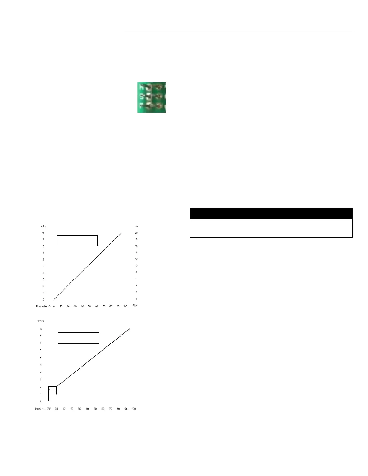
Remote PWM Signal Interface Board Details
Jumpers
M – Enables SET SPEED potentiometer
manual override (bypassed when
automation SIGNAL exceeds 0.2VDC).
S – Enables SET SPEED potentiometer reversal (used
when the set speed potentiometer is going to be adjusted
from the component side of the board).
P – Enables hysteresis option
With P Jumper: Configures the SIGNAL input to a 2-10v
range; corresponding to 0-100% motor speed request.
Signal with
“P” Jumper Out
Signal with
“P” Jumper In
Input / Output Control Signals
Input
Power Supply: 18-30 VAC, 60Hz
SIGNAL & COMMON: 0-10VDC = 0-100% PWM request
ECM supplied feedback: 5VDC (motor at rest or not
connected)
Output
PWM supplied to ECM: 18VDC (10mA max)
ON/OFF supplied to ECM: 18VDC (10mA max)
RPM & COMMON: 0-10VDC (5mA max) = 0-2000 RPM
(10 RPM increments)
FB-IOM-5.0 8-26-20
 Loading...