TKM, Inc MX170B NAV/COMM
3/20/06 2/3
Basic Operation
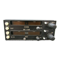
Refer to the photo for placement of the controls and displays.
The left hand COMM readout indicates the active COMM frequency; the right hand
readout indicates the standby one.
The left hand NAV readout indicates the active NAV frequency; the right hand readout
indicates the standby one.
A “Tic” readout is provided on the upper left hand corner of the first digit of each of the
four frequency readouts. The meaning of each Tic is –
Note that the standby Tics are, therefore, mutually exclusive. The Tic indicates which
frequency may be altered.
Power Application. The COMM volume control contains the master power switch and
activates both COMM and NAV functions. Power off is fully counter-clockwise. The
NAV volume control contains a power switch for remote NAV units.
Frequency Selection. The N-C button toggles between COMM or NAV standby
frequency selection. The frequency under control is indicated by the Tic. The MHz and
KHz controls can then be used to select a desired standby channel. When selecting a
standby COMM frequency, the 25 button is used to advance the frequency by 25 KHz.
After the desired frequency is entered into the standby position, it may be transferred to
the active position by pressing the flip-flop button between the two displays. Active and
standby will be interchanged each time the button is pressed.
Ident/Voice Selection. The VC-ID button can be used to select a filter in order to receive
voice signals on the NAV receiver. Its status is indicated by the Active NAV Tic. This
switch is also used for frequency storage (see below).
Test. The TEST button is a dual function switch. In normal operation, it is used to
override the squelch. This will verify receiver operation. It will also allow the reception
of weak signals. It is also used in frequency storage (see below).
 Loading...