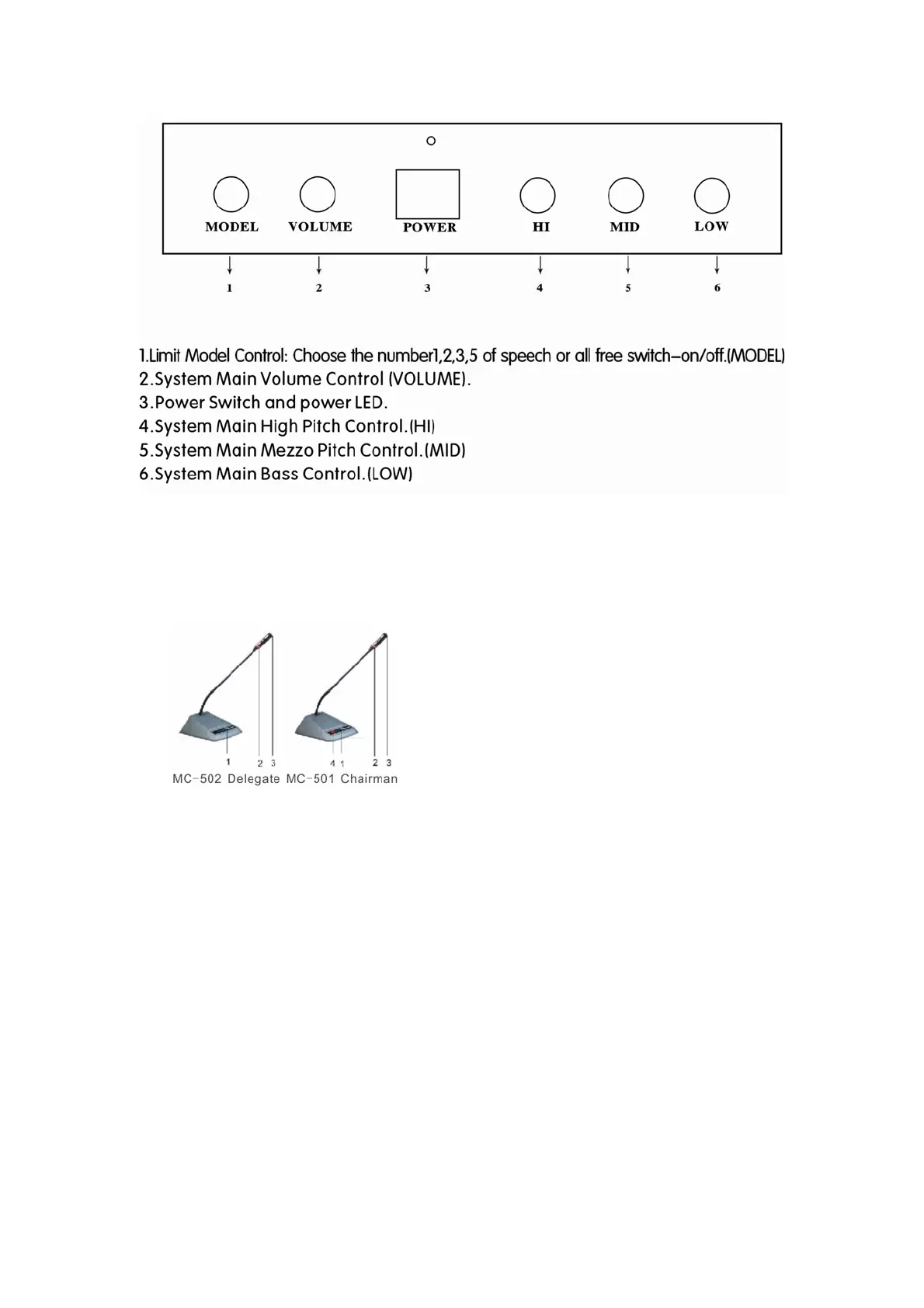
D. Schematic diagram of the microphone unit
1. ON/OFF button
2. Annular red indicator lamp
3. Unidirectional electret MIC
4. Priority button. Chairman unit can turn down delegate MIC by press the priority button.
E. Setting-up, debugging and using
1) Setting-up and debugging
1. Connect the first delegate or the chairman console to DELEGATE I or II on the rear
panel of the MC-500, and then connect other microphones to the first one by one in
serial, and each circuit can connect up to 25pcs. Please refer to diagram (1), (2).
2. Switch on the power of the main unit and see if the LED is lit.
3. Check if the whole system is functioning, press the on/off button of the microphones to
see if they can work properly.
4. Check if the priority button of the chairman can mute the delegates.
F. Connection with power amplifier
1. Turn the volume of the power amplifier to min, and connect it to “ LINE OUT” or
“ BALANCE OUT” on the main unit.
2. Tune on the power amplifier, switch on the microphones, testing and adjusting the
volume of the amplifier to the ideal level.
 Loading...