Injection Molding Machine Chapter 7
7-5
V3.0
Max. value 60E 90E 120E 150E 200E 250E 350E 500E 750E 1000E
Injection 120.0 150.0 180.0 180.0 250.0 300.0 350.0 400.0 450.0 520.0
Clamp 197.5 255.0 308.5 302.5 355.0 418.0 533.0 691.0 823.0 939.0
Ejector 80.0 80.0 100.0 100.0 120.0 140.0 180.0 200.0 240.0 300.0
Carriage 250.0 300.0 300.0 300.0 350.0 350.0 450.0 500.0 600.0 700.0
2.2 Adjustment of proportional valve
This adjustment is to make the output of proportional valve to match with the set value thus enabling
the machine to be in correct and smooth operation. Adjustment procedures are as follows:
A) Make sure that wire connection
of proportional valve is good and
the valve is still in normal
operation.
B) Open control box door(Power
is still “ON”).
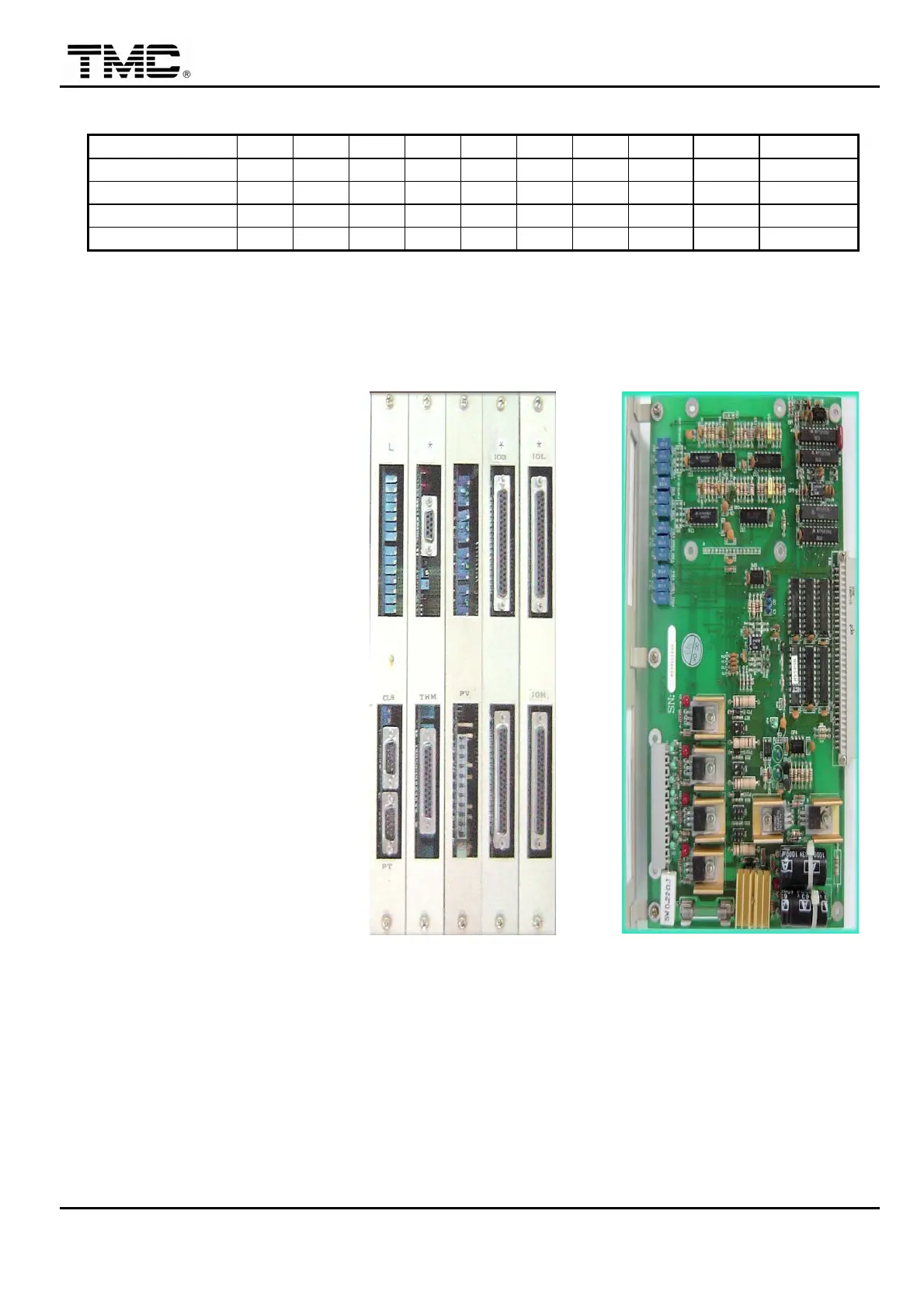
C) There is a total of 4 sets (3 per
set) variable resistors on
theM95PV board , 1 set o
proportional pressure flow valve
is controlled by 2 sets of variable
resistors.
D) There are 3 places on the upper
side of each set for pressure
adjustment, in sequence, min.
value (NULL)/dither frequency
( DITHER ) /max. value.
(SCALE), while 3 places on the
lower side of each set for flow
adjustment, in sequence, min.
value/dither frequency/max.
value.
Pressure
Unit 1
Flow
Pressure
Unit 2
Flow
Clockwise rotation: lower
Counter clockwise rotation:
higher
 Loading...