3-9
3
4st 2/2.5/3.5 2007
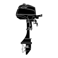
2. Remove lower unit installation bolts 3 and nut 4, and pull
lower unit ass'y downward to remove.
a Projecton c
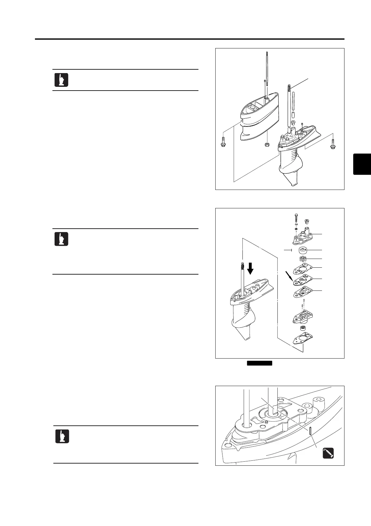
3. Remove bolt, and then, pump case (upper) 1 while pushing
drive shaft downward b.
4. Remove impeller 2.
5. Check pump case (upper) 1 for deformation. Replace if
necessary.
6. Check impeller 2, pump case liner 3 and guide plate 5 for
cracks and wear. Replace if necessary.
7. Check key 4 and drive shaft groove d for wear. Replace if
necessary.
8.
Reinstall the components removed. For details, refer to Chapter 6.
Check drive shaft spline a for adhesion of oil,
rust and wear.
• When removing or attaching water pump and
pump case (lower), be careful that the drive
shaft is not pushed up.
• Pushing up the drive shaft causes pinion (B)
gear to drop into the gear case.
• When replacing impeller, install it so that it rotates
in clockwise direction.
• Apply grease to the key to prevent it from
dropping when attaching.
Do not reuse.
MFS2sec03070524.qxd07.5.243:16 PM ページ9
 Loading...