Do you have a question about the Tokyo Sokki Kenkyujo TC-32K and is the answer not in the manual?
| Number of channels | 32 |
|---|---|
| Resolution | 16-bit |
| Input voltage range | ±10 V |
| Power supply | AC adapter (100 to 240 VAC), DC power (10 to 30 VDC) |
| Operating temperature range | 0°C to 50°C |
| Dimensions | 290(W) × 110(H) × 240(D) mm |
| Weight | Approx. 3.2 kg |
| Communication Interface | Ethernet, USB |
| Storage temperature range | -20°C to 60°C |
General introduction to the TC-32K handheld data logger, its features, and capabilities.
Key features of the TC-32K, including measurement types, connectivity, and operational highlights.
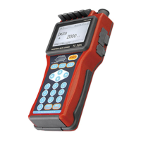
Detailed description of the TC-32K's front, side, top, bottom, and back components and ports.
Important precautions and guidelines for safely and correctly operating the instrument.
Information on setting batteries, operating time, and connecting the AC adapter for power.
Instructions for correct grounding and lightning protection during field measurements.
Overview of the startup screen and the general screen configuration for navigation and settings.
Explanation of the TC-32K's operation system, including key switches and the key lock function.
Explains how to connect sensors using terminal blocks and NDIS connectors, detailing wire connection procedures.
Describes the main monitor screen, its components, and communication indicators.
Details value monitor, waveform monitor, and meaning of displayed values, including examples.
Explains how to memorize current values as initial values for measurement and compensation.
Covers setting measurement modes (single, multi-channel, inclinometer) and selecting channels for monitoring.
Instructions for manual and automatic recording of measurement data to memory or CF card.
Explains the indicators on the sub LCD and their meanings, related to operation status.
Outlines the chapter's topics: sensor, automatic measurement, and various checks.
How to set sensor modes, coefficients, and units for different sensor types.
Setting parameters like coefficient, indication digits, and units for physical quantity display.
Setting Reference Junction Compensation for thermocouple temperature measurements.
Reading sensor settings from TEDS-compatible transducers and applying them.
How to change the measurement mode based on connected devices or desired measurement type.
Switching between displaying values with or without initial value subtraction.
Configuration for interval measurement, real-time start, Goto Step, and sleep function.
Performing insulation, resistance, dispersion, lead wire, bridge output, and coefficient checks.
Settings for simple measure, Comet, power frequency, initial-in permission, and burnout check.
Explains operations for managing data from internal memory and CF card.
Details data memory structure, readout, deletion, and setting data numbers.
How to read, delete data, set file names/formats, and format the CF card.
Instructions for copying measurement data from data memory to a CF card.
Specifies where measurement data is recorded: data memory, CF card, or both.
Explains settings for external devices like PCs, printers, and indicators.
Configuring baud rate, data bits, parity, stop bit, and timeout for RS-232C communication.
Connecting external devices and specifying data output destinations and procedures.
Setting the data output format, including CSV and TDS formats, and header/time data inclusion.
Setting communication conditions for connecting an external indicator.
Important considerations for setting up the TC-32K with an optional printer for correct printing.
Using a PC or modem to control the TC-32K remotely, including configuration and functions.
Covers date/time, language, maintenance, and factory settings.
Setting the instrument to turn off automatically after a period of inactivity.
Shows the software version and serial number of the TC-32K.
Adjusting the instrument's date and time settings for accurate logging.
Choosing between Japanese and English as the display language for the instrument.
Settings for LCD backlight, brightness, contrast, buzzer volume, and software upgrading.
Restoring the TC-32K to its original factory default settings.
Options and methods to increase measurement points using switching boxes or inclinometer adapters.
Connecting and using the CSW-5B switching box for 5-point measurements.
Connecting and using the IA-32 adapter for 2-axis inclinometer measurements.
Explains various wire connection methods for strain gauges (4-wire, 3-wire, half, full bridge).
Discusses sensitivity drop in constant voltage/current methods due to sensor cable extension.
Details Comet compensation methods (NON, A, B) for strain measurement errors.
Calculating lead wire resistance for compensation using specific equations and measurements.
Explains measurement principle and compensation operations for the 1-gauge 4-wire method.
Detailed specifications including measurement points, applicable sensors, ranges, and accuracy.
Lists the items included in the TC-32K package.
Lists optional accessories available for purchase to enhance TC-32K functionality.
Provides physical dimensions and an overview drawing of the TC-32K instrument.
Lists error messages, their classifications, and provides explanations and solutions.
