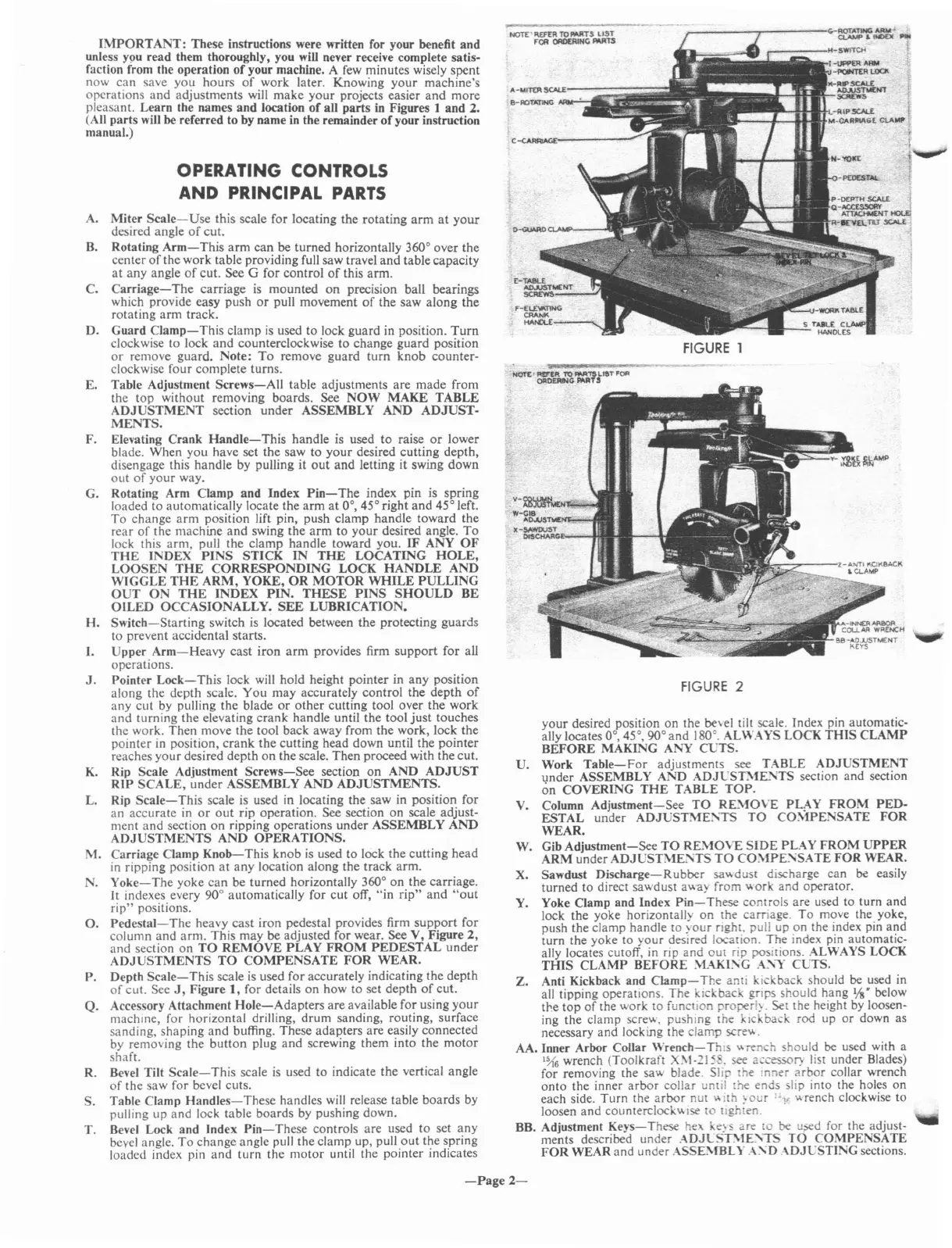
your
desired position
on
the
be\el
tilt scale. Index pin automatic-
ally locates
0°,45°,90°
and
180°. ALWAYS
LOCK
THIS
CLAMP
BEFORE
MAKING
ANY
CCTS.
U.
Work
Table-For
adjustments see TABLE
ADJUSTMENT
under
ASSEMBLY AND ADJCST:\1E.....
TS
section
and
section
on
COVERING
THE
TABLE
TOP.
V. Column
Adjustment-See
TO
RE:\10VE
PLAY
FROM
PED-
ESTAL
under
ADJUSTME:\TS
TO
CO"-1PENSATE
FOR
WEAR.
W. Gib
Adjustment-See
TO
RE:\10VE
SIDE
PLAY
FROM
UPPER
ARM
under ADJUST"-iE:'\TS
TO
CO:\fPE:\SA
TE
FOR
WEAR.
X. Sawdust
Discharge-Rubber
sa",duSI discharge
can
be easily
turned
to
direct sawdust away from work and operator.
Y. Yoke Clamp
and
Index
Pin-These
controls are used to turn
and
lock the yoke horizontally
on
the carriage.
To
move the. yoke,
push the clamp handle
to
your
right, pull up on the index pm a':ld
turn
the yoke to
your
desired location. The index pin automatic-
ally locates cutoff, in
rip
and
out
rip positions. ALWAYS LOCK
THIS
CLAMP
BEfORE
:\1AKI:\G A
...
"1'
CLTS.
Z.
Anti Kickback and
CIamp-
The anii kickback should be used in
all tipping operations. The kickbac. grips should hang
Vs"
below
the
top
of
the work
to
function
properi~.
Set the height by loosen-
ing the clamp screw, pushing the kickback rod up
or
down as
necessary
and
locking Ihe clamp scre"'.
AA. Inner Arbor Collar
Wrem:h-
Tnl;
wrench should be used with a
1~6
wrench (Toolkraft
X\I-215
. see accessory list under Blades)
for removing the saw blade. Sli the
Inner
arbor
collar wrench
onto
the inner
arbor
collar until
the
ends slip into the holes
on
each side.
Turn
the
arbor
nut
'ilh
~o
r
"1;
"'rench clockwise
to
loosen
and
counterclock"'lsc
to
lighten.
BB. Adjustment
Keys-These
hex
ke~
s are
to
be
u.><:d
for the adjust-
ments described under
.-\DJCST\lE:\iS
TO
COMPENSATE
FOR
WEAR and under ASSE..'\fBLY .-\:\D
:\DJCSTING
sections.
FIGURE
2
"'-=--'''"''41''
~~--_H-SWfTCH
1
-tJIPfER
ARM
"-rOM"tR
LOCJ\
K-~~Nl
SCREWS
I
L-A,IP5CAl.E t
M-CARRtAGE
CLAW
i'
r-------,...------
..
-~"'f~
.....
!
FIGURE
1
C-eARRI.'o<>E:-----
NOT£'
REF£R TOMRT.s
LIST
fOIl
ORDERING
""'1S
OPERATING CONTROLS
AND PRINCIPAL
PARTS
IMPORTANT:
These instructions were written for your benefit
and
unless
Y9U
read them thoroughly, you will never receive complete satis-
faction from the operation
of
your machine. A few minutes wisely spent
now
can
save
you
hours
of
work later. Knowing
your
machine's
operations
and
adjustments will
make
your
projects easier
and
more
pleasant. Learn the names
and
location
of
all
parts
in Figures 1
and
2.
(All
parts
will be referred to by name in the remainder
of
your instruction
manual.)
A.
Miter
Scale-Use
this scale for locating the
rotating
arm
at
your
desired angle
of
cut.
B.
Rotating
Arm-This
arm
can
be
turned
horizontally 360° over
the
center
of
the work table providing full saw travel
and
table capacity
at
any angle
of
cut.
See G for
control
of
this
arm.
C.
Carriage-
The
carriage is
mounted
on
precision ball bearings
which provide easy push
or
pull movement
of
the saw along
the
rotating
arm
track.
D.
Guard
Clamp-This
clamp
is
used
to
lock guard in position.
Turn
clockwise
to
lock
and
counterclockwise
to
change
guard
position
or
remove guard. Note:
To
remove
guard
turn
knob
counter-
clockwise
four
complete turns.
E. Table Adjustment
Screws-All
table adjustments are
made
from
the
top
without removing boards. See
NOW
MAKE
TABLE
ADJUSTMENT
section
under
ASSEMBLY
AND
ADJUST-
MENTS.
F. Elevating
Crank
Handle-This
handle is used
to
raise
or
lower
blade. When
you
have set
the
saw
to
your
desired cutting depth,
disengage this
handle
by pulling
it
out
and
letting
it
swing
down
out
of
your
way.
G. Rotating Arm Clamp
and
Index
Pin-The
index pin is spring
loaded
to
automatically locate the
arm
at
0°, 45° right
and
45° left.
To
change
arm
position lift pin, push clamp handle toward
the
rear
of
the machine
and
swing
the
arm
to
your
desired angle.
To
lock this
arm,
pull
the
clamp
handle
toward you.
IF
ANY
OF
THE
INDEX
PINS
STICK
IN
THE
LOCATING
HOLE,
LOOSEN
THE
CORRESPONDING
LOCK
HANDLE
AND
WIGGLE
THE
ARM,
YOKE,
OR
MOTOR
WHILE
PULLING
OUT
ON
THE
INDEX
PIN.
THESE
PINS
SHOULD
BE
OILED
OCCASIONALLY.
SEE
LUBRICATION.
H.
Switch-Starting
switch is located between
the
protecting
guards
to prevent accidental starts.
I.
Upper
Arm-Heavy
cast
iron
arm
provides firm
support
for
all
operations.
J.
Pointer
Lock-This
lock will hold height pointer in
any
position
along the depth scale.
You
may
accurately
control
the
depth
of
any
cut
by pulling the blade
or
other
cutting tool over the work
and
turning the elevating
crank
handle until
the
tool
just
touches
the work.
Then
move
the
tool back away from
the
work, lock
the
pointer in position,
crank
the
cutting head down until the
pointer
reaches
your
desired depth
on
the scale.
Then
proceed with the cut.
K. Rip Scale Adjustment
Screws-See
section
on
AND
ADJUST
RIP
SCALE,
under
ASSEMBLY
AND
ADJUSTMENTS.
L. Rip
Scale-This
scale is used in locating the saw in position for
an
accurate
in
or
out
rip operation. See section
on
scale adjust-
ment
and
section
on
ripping operations
under
ASSEMBLY
AND
ADJUSTMENTS
AND
OPERATIONS.
M.
Carriage Clamp
Knob-This
knob
is
used to lock
the
cutting
head
in ripping position
at
any
location along the track arm.
N.
Yoke-The
yoke
can
be turned horizontally 360°
on
the
carriage.
It
indexes every 90° automatically for
cut
off,
"in
rip"
and
"out
rip"
positions.
O.
Pedestal-The
heavy
cast
iron
pedestal provides firm
support
for
column
and
arm.
This may be adjusted for wear. See V, Figure
2,
and
section
on
TO
REMOVE
PLAY
FROM
PEDESTAL
under
ADJUSTMENTS
TO
COMPENSATE
FOR
WEAR.
P. Depth
Scale-This
scale
is
used for accurately indicating
the
depth
of
cut. See
J,
Figure
1,
for details
on
how to set depth
of
cut.
Q.
Accessory Attachment
Hole-Adapters
are
available for using
your
machine for horizontal drilling,
drum
sanding, routing, surface
sanding,'shaping
and
buffing. These adal?ters
are
easily connected
by removing the
button
plug
and
screwing them
mto
the
motor
shaft.
R. Bevel Tilt
Scale-This
scale
is
used
to
indicate the vertical angle
of
the saw for bevel cuts.
S. Table Clamp
Handles-These
handles will release table
boards
by
pulling up
and
lock table boards by pushing down.
T. Bevel Lock and Index
Pin-These
controls are used
to
set
any
bevel angle.
To
change angle pull
the
clamp up, pull
out
the spring
loaded index pin
and
turn
the
motor
until the pOinter indIcates
-Page
2-
 Loading...