ParI
No.
Name
of
ParI
GRINDING
WHEEL
XM-1076 Grinding
Wheel-7'
dia.,
'Ys'
hole,
Y2'
face.
60
grit aluminum oxide vitrified .
WORK S
PPORT
STAND
25
Work Support Stand .
JOINTER
HEAD
900-456
2'
long x
2'
dia. cutter head .
JOI
TER AND
SHAPER
FENCE
900-457 Fence Assembly .
SAFETY PRECAUTIONS
1.
Think before acting.
2.
Avoid
wearing long neckties, long sleeves
or
other loose clothing
when
working with your machine.
3.
Use the saw guard
at
all times.
4.
Make sure all adjustment clamps are locked firmly before making
any cuts.
5. Keep saws and other cutting tools sharp.
6.
Use a push stick for ripping narrow pieces.
7.
Never make adjustments or setup changes while the blade
is
running.
8.
Aim
the rubber sawdust discharge elbow away from the operator.
9. Support long work properly with Model
25
Stand.
10.
Keep your working table clear and uncluttered.
ParI
No.
Name
of
ParI
ADAPTORS
900-435
Adaptor-for
use with all three lip shaper knives
and buffing and polishing kit .
Includes the adaptor, 3 spacer collars
Y2',
1,4'
and
Ys'
wide, two cup washers for use on buffing
wheels and
Y2'·20 locking nut.
900·440
Adaptor-for
use with all router bits, dovetail
bits, rotary sander. rotary planer and drum
sanders .
Includes the adaptor, two sleeves
<Y2'
to
~6'
dia.)
<Y2'
to 1,4' dia.) and 2 locking screws.
900·450
Adaptor-for
use with female
33
Jacobs Taper
Chucks .
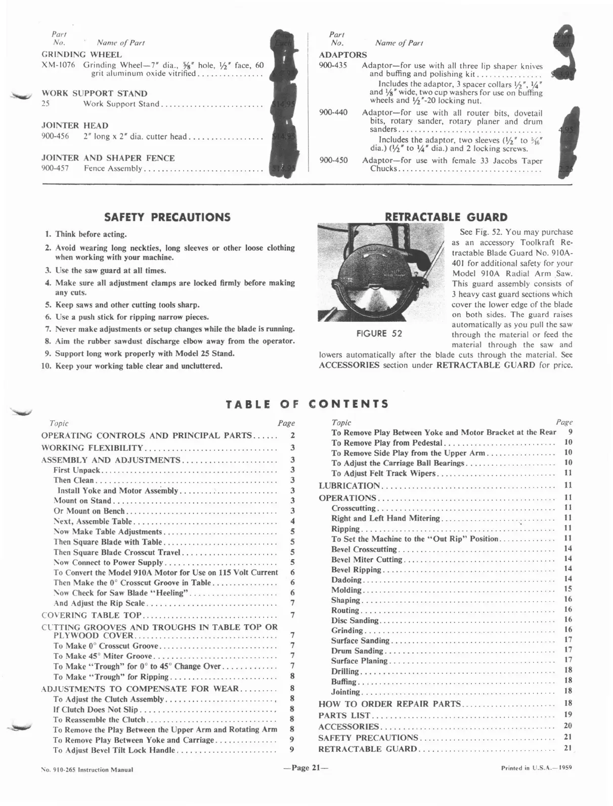
See Fig.
52.
You may purchase
as
an
accessory Toolkraft Re·
tractable Blade
Guard
No. 910A·
401
for additional safety for your
Model 910A Radial Arm Saw.
This guard assembly consists
of
3 heavy cast guard sections which
cover the lower edge
of
the blade
on both sides. The guard raises
automatically as you pull the saw
FIGURE
52
through the material
or
feed the
material through the saw and
lowers automatically after the blade cuts through the material.
See
ACCESSORIES section under RETRACTABLE GUARD for price.
TABLE
OF
CONTENTS
Topic Page
OPERATING
CONTROLS
AND
PRINCIPAL
PARTS......
2
WORKING FLEXIBILITY. . . . . . . . . . . . . . . . . . . . . . . . . . . . . . . . 3
ASSEMBLY AND
ADJUSTMENTS.
. . . . . . . . . . . . . . . . . . . . . . 3
First Unpack. . . . . . . . . . . . . . . . . . . . . . . . . . . . . . . . . . . . . . . . . . . 3
Then Clean. . . . . . . . . . . . . . . . . . . . . . . . . . . . . . . . . . . . . . . . . . . . 3
Install Yoke and
Motor
Assembly
:.
. . . . . . . . . . . . . . 3
\-Iount
on
Stand.
. . . . . . . . . . . . . . . . . . . . . . . . . . . . . . . . . . . . . . . 3
Or
Mount
on
Bench. . . . . . . . . . . . . . . . . . . . . . . . . . . . . . . . . . . . . 3
:"ext, Assemble Table. . . . . . . . . . . . . . . . . . . . . . . . . . . . . . . . . . . 4
:"ow Make Table Adjustments. . . . . . . . . . . . . . . . . . . . . . . . . . . . 5
Then Square Blade with Table. . . . . . . . . . . . . . . . . . . . . . . . . . . . 5
Then Square Blade Crosscut Travel. . . . . . . . . . . . . . . . . . . . . . . 5
:"ow Connect to Power Supply. . . . . . . . . . . . . . . . . . . . . . . . . . . 5
To
Convert the Model 910A Motor for Use on 115 Volt Current 6
Then Make the 0° Crosscut Groove
in
Table. . . . . . . . . . . . . . . . 6
:"ow Check for Saw Blade
"Heeling".
. . . . . . .
..
6
And Adjust the Rip Scale. . . . . . . . . . . . . . . . . . . . . . . . . . . . . . . 7
COVERING TABLE
TOP..
..
. . . .
...
.
..
.
..
. .
...
. . . . . .
..
.
..
7
CLTTING GROOVES AND
TROUGHS
IN TABLE
TOP
OR
PL
YWOOD
COVER...................................
7
To
Make 0° Crosscut Groove. . . . . . . . . . . . . . . . . . . . . . . . . . . . . 7
To Make 45° Miter Groove. . . . . . . . . . . . . . . . . . . . . . . . . . . . . . 7
To Make
"Trough"
for 0° to 45° Change Over. . . . . . . . . . . . . 7
To Make
"Trough"
for Ripping. . . . . . . . . . . . . . . . . . . . . . . . . . 8
ADJUSTMENTS
TO
COMPENSATE
FOR
WEAR. . . . . . . . . 8
To Adjust the Clutch Assembly. . . . . . . . . . . . . . . . . . . . . . . . . . • 8
If Clutch Does Not
Slip.
. . . . . . . . . . . . . . . . . . . . . . . . . . . . . . . • 8
To Reassemble the Clutch. . . . . . . . . . . . . . . . . . . . . . . . . . . . . . . . 8
To Remove the Play Between the Upper Arm and Rotating Arm 8
To Remove Play Between Yoke and Carriage. . . . . . . . . . . . . . . 9
To Adjust
Bevel
Tilt Lock Handle. . . . . . . . . . . . . . . . . . . . . . . . 9
Topic Page
To Remove Play Between Yoke and Motor Bracket
at
the Rear 9
To Remove Play from Pedestal. . . . . . . . . . . . . . . . . . . . . . . . .
..
10
To Remove Side Play from the Upper
Arm.
. . . . . . . . . . . . . .
..
10
To Adjust the Carriage Ball Bearings. . . . . . . . . . . . . . . . . . . . . .
10
To Adjust Felt Track Wipers. . . . . . . . . . . . . . . . . . . . . . . . . . .
..
II
LUBRICATION.
11
OPERATIONS...........................................
11
Crosscutting. . . . . . . . . . . . . . . . . . . . . . . . . . . . . . . . . . . . . . . . . . .
11
R~gh~
and Left Hand Mitering ; . . . . . .
..
11
Ripping. . . .
..
. . . . . . . . . . . . . . . . . . . . .
.. ..
. .
..
11
To Set the Machine to the
"Out
Rip" Position. . . . . . . . . . . .
..
11
Bevel Crosscutting. . . . . . . . . . . . . . . . . . . . . . . . . . . . . . . . . . . .
..
14
Bevel Miter Cutting. . . . . . . . . . . . . . . . . . . . . . . . . . . . . . . . . . . . .
14
Bevel Ripping. . . . . . . . . . . . . . . . . . . . . . . . . . . . . . . . . . . .
14
Dadoing...............................................
14
Molding...............................................
15
Shaping. . . . . . . . . . . . . . . . . . . . . . . . . . . . . . . . . . . . . . . . . . . . .
..
16
Routing.
.. ..
16
Disc Sanding. . . . . . . . . . . . . . . . . . . . . . . . . . . . . . . . . . . . . . . . .
..
16
Grinding. . . . . . . . . . . . . . . . . . . . . . . . . . . . . . . . . . . . . . . . . . . .
..
16
Surface Sanding. . . . . . . . . . . . . . . . . . . . . . . .
..
. . . . . . . . .
..
17
Drum Sanding _. .
..
17
Surface Planing. . . . . . . . . . . . . . . . . . . . . . . . . . . . . . . . . . . . . .
..
\7
Drilling. . . . . . . . . . . . . . . . . . . . . . . . . . . . . . . . . . . . . . . . . . . . .
..
18
Buffing. . . . . . . . . . . . . . . . . . . . . . . . . . . . . . . . . . . . . . . . . . . . . .
..
18
Jointing...............................................
18
HOW
TO
ORDER
REPAIR
PARTS.......................
18
PARTS
LIST.
. . . . . . . . . . . . . . . . . . . . . . . . . . . . . . . . . . . . . . . . .
..
19
ACCESSORIES.
. . . . . . . . . . . . . . . . . . . . . . . . . . . . . . . . . . . . . . .
..
20
SAFETY
PRECAUTIONS.
. . . . . . . . . . . . . . . . . . . . . . . . . . . . . .
..
21
RETRACTABLE
GUARD.
. . .
.. ..
. . .
..
. . . . . . . . . . . . . . . . . .
..
2\
",,0.910-265 Instruction
Manual
-Page
21-
Prinlod
in
U.S.A.-1959
 Loading...