Grinding Tapered Cutters
Circular Grinding of sice and End Cutting Eiges
Tapered cutters can be ground to size in the machine without the use of any measuring instrument, ex-
ceptforthescalesprovidedonthemahcine.Forcirculargrindingoperationsofproledcuttersfollowthis
procedure :
Setup Operations
1. Engage pin C into long-slot.
2. Align the cutter lip by means of gauge C. Grip the cutter and return the C gauge
3. Draw index pin P out of the slot hole to enable collet bearing to be rotated throuhg 360°. Release
clamping levers T2, T3, T6. Set scale S2 and F at zero. Tighten clamping levers T4, T2, T3, T6
see Fig.4
4, Release clamping lever T7; bring cutter diameter into light contact with grinding wheel; tighten clamp
ing lever T7, taking care to keep Index mark of vertical swivel mount aligned with tubular guide;
release clamping lever T4, see Fig. 4. .
5. a.No.6prole(Fig.1and2):ReleaseclampingleverT1;rotateknurledknobS4toshiftcrossslideto
the right by one-half of dia, of the taper(‘a’ in Fig. 9. For this purpose use cross slide vernier scale T.
Tighten clamping lever T1
b. No.6prole(Fig.aand2):ReleaseclampingleverT1;rotateknurledknobS4toshiftcrossslideto
the right by the desires amount “a” (use cross slide vernier scale T). Tighten clamping lever T1.
c. No.7prole(Fig.land3):Setcrossslidevernierscaleatzero.
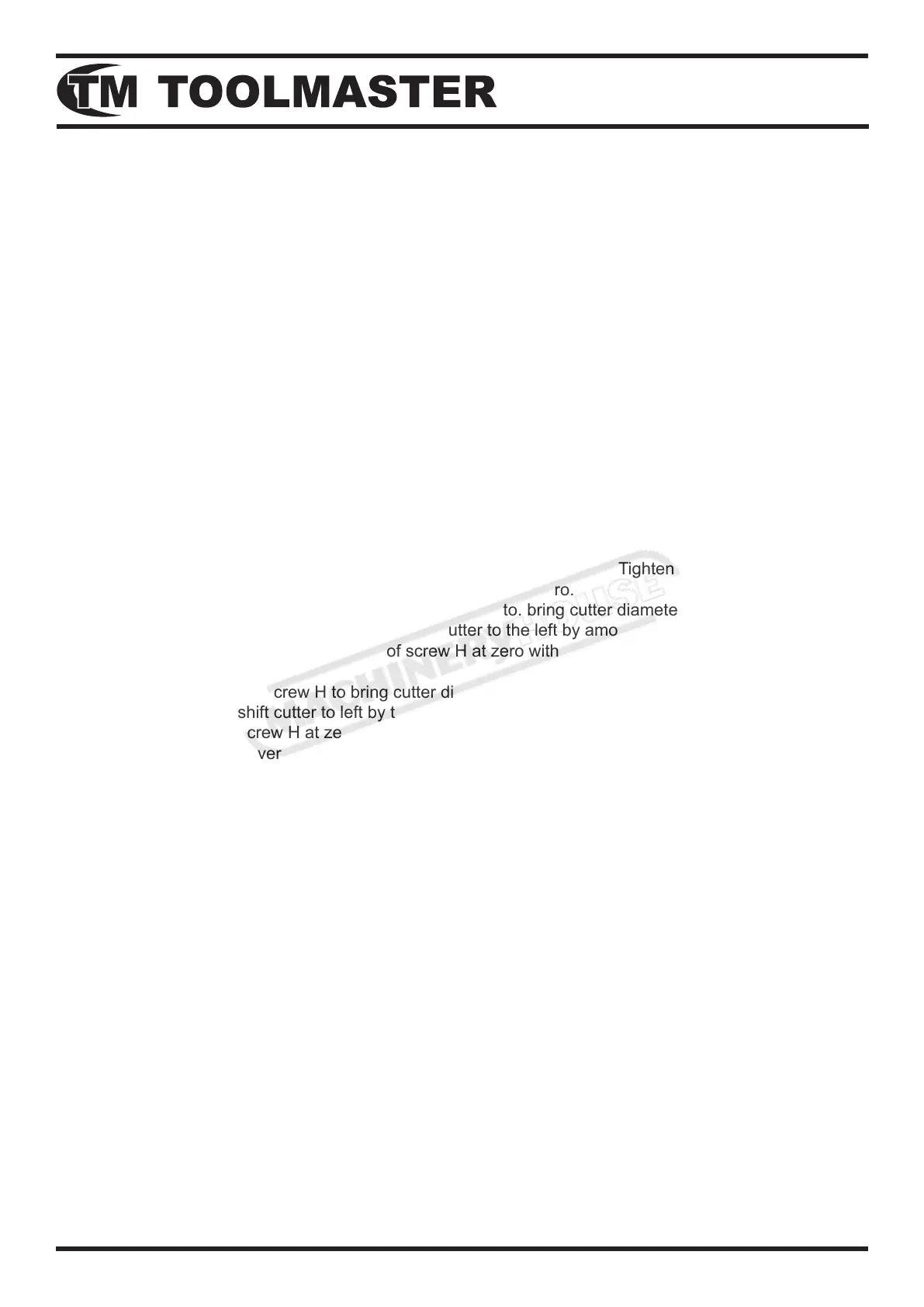
6,a.No.5and7proles:RotateneadjustmentscrewHto.bringcutterdiameterintolightcontactwith
grinding wheel: again rotate screw H to shift cutter to the left by amount x, = D/2— a. To facilitate
this setting operation, set scale drum of screw H at zero without disturbing the setting of the screw
(see Fig, 4).
b. No.6prole:RotatescrewHtobringcutterdiameterintolightcontactwithgrindingwheel;again
rotate screw H to shift cutter to left by the amount x= D/2— (a+ r). To facilitate this setting operation
set scale drum of screw H at zero without disturbing the setting of the screw (see Fig. 4).
Release clamping lever T3 and rtotate the swivel arm through90°.Release clamping lever T5 and
rotate index head slide micrometer screw S to advance end face of the cutter towards grinding
wheel. Wheel tapered cutters are to be resharpened, the Iength of the cutting edge at the end of the
cutter should be made greater than the small diameter of the tapered portion.
8. Release clamping lever T6; hold index drum F against its stop and counting from the zero position, set
swivel arm at the desired taper angle; tighten clamping lever T3 and T6, see Fig. 6.
9. a.No.5prole:SlowlyreturnstopscrewGandcontinuouslyratatethecolletbearingthrough360°
to advance the cutter past the grinding wheel. Prior to the circular grinding operation ratate
the adjustment screw H to shift the cutter to the right; then advance the cutter towards the wheel
by small increment unit the desired size has been obtained (see Fig. 6).
b. No.6and7proles:ReleaseclampingleverT3;rstslowlyreturnstopscrewG,thenslowlyswing
the swivel arm while continuously rotating the collet bearing through 360° to move the cutter past
thewheelandthustocirculargrindingoperationrotateneadjustmentscrewHtoshiftthecutter
to the right; then advance the cutter towards the wheel by small Increments until the desired
size has been obtained (see Fig. 7 A 8).
 Loading...