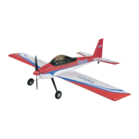
The provided document is an assembly and instruction manual for the "Thunder" R/C Aerobatic Sports Aircraft, manufactured by TOP RC HOBBY.
The Thunder is a radio-controlled model aircraft designed for aerobatic sports flying. It is constructed from "EPOFLEXY," a tough and durable material, which contributes to its robustness. The manufacturer emphasizes that while it's durable, a range of spares is available for quick repairs in case of "less than perfect" landings. The aircraft is capable of a wide range of aerobatic maneuvers, appealing to experienced pilots, but can also be flown with reduced control throws for a more stable and predictable flight, suitable for sports flyers. It features a high brightness LED lighting system.
Key Features:
- Powerful Brushless Motor
- 40A Brushless Electronic Speed Controller
- Efficient 2 Blade Propeller
- Pre-Installed servos
- "Live" Control Surface Hinges
- Durable "EPOFLEXY" Construction
- Steerable Tail Wheel
- Superb Flight Performance
- High Brightness LED Lighting System
Technical Specifications:
- Wingspan: 1380mm
- Length: 1130mm
- Weight: 1480g
- Motor: 3720 ~ 880kv (Brushless)
- ESC: 40A Brushless
- Servos: 2 x 17g, 2 x 9g
- Battery Required: 11.1V 2200mAh-3300mAh (Not Included)
Safety Precautions:
The manual stresses that this is not a toy and requires skill to fly. It is not recommended for beginners without assistance from an experienced model pilot and should not be operated by children without suitable adult supervision. Users are advised not to repair or modify the aircraft with non-factory parts. Flying is prohibited over roads, railway lines, near power lines, airports, or in excessively strong winds, rain, or thunderstorms. The model should not be flown or launched towards people, and hands and face must be kept away from the rotating propeller. Regular checks of all fixings and fasteners are strongly recommended to prevent crashes or injuries. Only 2.4GHz radio equipment is recommended.
Disclaimer:
The manufacturer and distributor disclaim all responsibility for injury or property damage resulting from the use of the product, as the owner/pilot assumes all responsibility. It is crucial to follow all assembly and setup instructions to avoid loss of control and potential crashes.
EPOFLEXY Material:
"EPOFLEXY" is highlighted as a very tough and durable material. When using screws with EPOFLEXY components, it's important to tighten them sufficiently for a firm fixing, but avoid excessive tightening which could compress the foam and damage or distort the part. Regular checks of all fixings are recommended for security and safety.
Assembly and Usage Features:
The manual provides detailed, step-by-step instructions for assembly:
- Undercarriage: Fixed with four 2.6 x 12mm self-tapping screws. The legs are angled towards the front of the fuselage.
- Horizontal Tail-Plane: A moulded tab at the fuselage end must be removed. The tail-plane slides into a fuselage slot, aligning holes. Foam glue can be used for maximum security.
- Vertical Fin & Rudder: Installed into a fuselage slot, ensuring the tail-wheel control wire is correctly located in the rudder slot. Foam glue can also be used here.
- Tail-Plane Fixing: The horizontal tail-plane and vertical fin are secured with two 2.6 x 35mm screws. Screws must be tight but not over-tightened.
- Tail Control Horns: Rudder and elevator snap-links connect to their respective control horns. Minor adjustments for neutral positions can be made by rotating the plastic link on the push-rod. Links must be securely "snapped" closed.
- Wing Assembly: A 500mm aluminum wing joining spar slides into one wing panel, then the small plywood wing locking plate is inserted. The second wing panel slides onto the spar. Wires must be routed correctly. Foam glue can be used for security. The two black aileron servo plugs connect to a Y-lead. The red and black wires for the LED lighting system connect to another Y-lead. Both Y-leads thread through the fuselage and plug into the receiver.
- Wing Fixing: The moulded wing cowling secures the wing to the fuselage. It fits one way, with the cutout towards the front. Two M4 x 55mm screws are used at the front, and one M4 x 38mm screw at the rear.
- Receiver Installation: The speed controller connects to the throttle channel. Rudder and elevator servos connect to their channels. The aileron Y-lead connects to the aileron channel, and the lights Y-lead to any spare receiver channel. A moulded recess accommodates most 2.4GHz receivers. The receiver should be securely positioned with self-adhesive "Velcro," following manufacturer recommendations for positioning and aerial routing.
- Propeller & Spinner: Involves sliding the aluminum propeller adaptor onto the motor shaft, followed by the tapered aluminum driver and plastic spinner back plate. The propeller is then fitted with a washer and securing nut. Tightening the nut clamps the adaptor to the motor shaft. The front section of the plastic spinner is attached with two screws. It is emphasized that the propeller must be securely fixed to prevent serious injury.
- Propeller Rotation: Double-check that the propeller is securely fixed and rotates in the correct direction (clockwise when standing behind the plane).
- Battery Installation: The battery is installed by removing the upper canopy (held by magnets). The flight battery (not included in PNP versions) connects to the factory-fitted "T" style connector. The battery must be secured with Velcro straps, and the canopy must be secure before flight. Self-adhesive Velcro on the battery and tray is recommended for added security.
- Control Surface: All control surfaces must be centered and respond correctly to transmitter inputs. Adjustments can be made by rotating plastic control horns on the push-rods. The servo reversing function on the transmitter can be used if controls respond incorrectly. All plastic links must be "snapped" closed, and hinges secure. Foam glue can be used if hinges are not firmly attached.
- Recommended Deflections:
- Ailerons: 15mm each way
- Elevator: 20mm each way
- Rudder: 28mm each way
- Experienced pilots may increase these movements after initial flight testing.
- Centre Of Gravity (CG): Crucial for control. The recommended balance point, with battery, is 80-100mm back from the leading edge of the wing for initial flights. Experienced pilots may move the balance point further back after initial flight testing.
Parts List (with part numbers):
- Top087001: FUSELAGE
- Top087002: MAIN WING
- Top087003: HORIZONTAL TAIL
- Top087004: RUDDER AND FIN
- Top087005: Cabin BLACK
- Top087006: PLASTIC WING JOINERS
- Top087007: SCREW set for main wing
- Top087008: Out runner brushless 3720-880KV
- Top087009: 40AMP ESC
- Top087010: PROP ADAPTOR
- Top087011: COWLING
- Top087012: LAND GEAR SET
- Top087013: PROPELLOR 12 X 8
- Top087014: Spinner
- Top087015: WING CONNECTING ROD
- Top087016: 9G SERVO
- Top087017: 17G SERVO
The manual concludes with contact information for Shenzhen Top RC Hobby Tech Co., Ltd.