2.
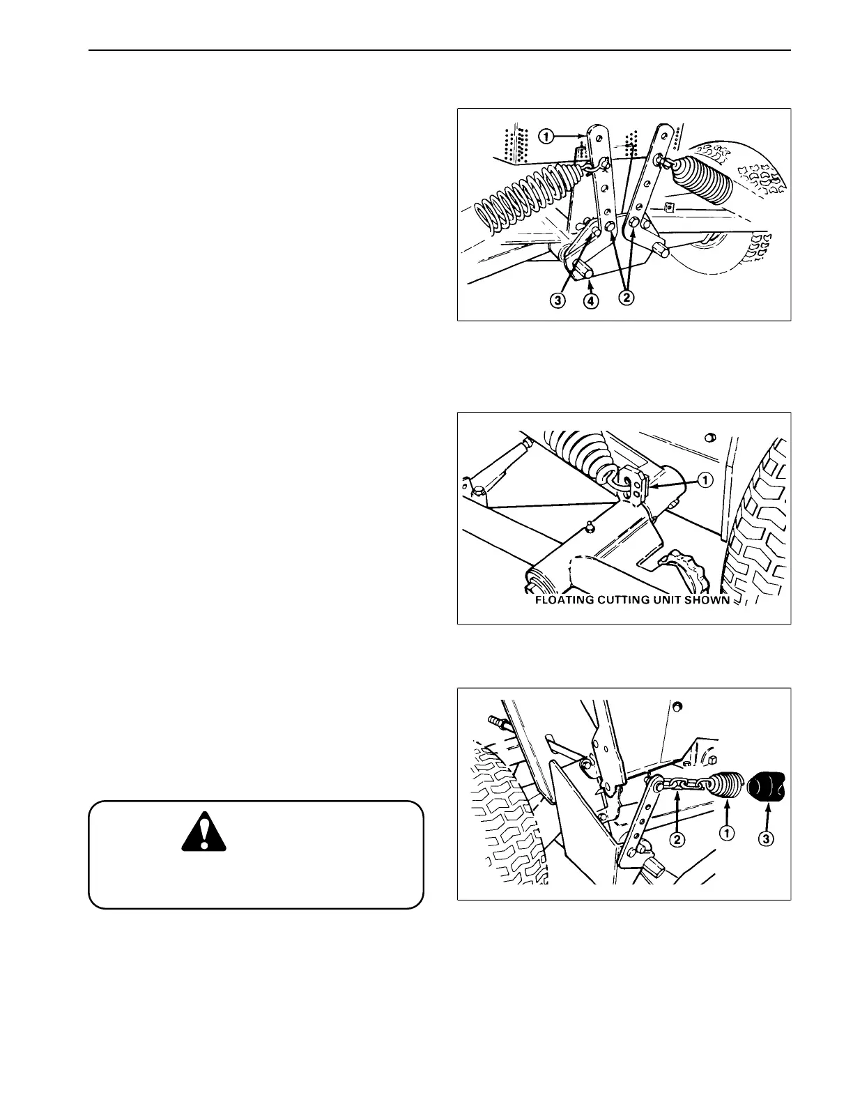
Counterbalance Spring Installation (Figs. 16, 17, 18)
1. Remove capscrew securing counterbalance arm to
frame.
2. Remove hairpin cotter and clevis pin next to arm.
3. Pivot front arms outward and rear arm inward.
4. Hook one end of spring into second hole (from
bottom) on cutting unit lift tab.
Note: On rear counterbalance spring install vinyl cover
over spring before installing.
5. On front cutting units secure other end of spring to
appropriate hole (see chart below) on counterbalance
Figure 16
arm with clevis, clevis pin and hairpin cotter.
1. Counterbalance arm 3. Capscrew, (2 ) flatwashers,
6. On rear cutting unit secure other end of spring to
2. Capscrew securing 3. spacer, nut
counterbalance arm 4. Counterbalance arm pivot hex
appropriate hole in counterbalance arm with (2) chain
links, (5, 8 & 11 Blade Floating Cutting units) or (3) chain
links (5 Blade Fixed Cutting units), clevis, clevis pin and
hairpin cotter.
A. Bottom hole — for 5 blade reel application
B. Middle hole — for 8 blade reels without baskets
C. Top hole — for 8 blade reels using baskets
IMPORTANT: These are recommended settings. Re-
adjust spring positions to attain optimum perform-
ance . By rai s i ng spri ng loc a ti ons on
counterbalance arms, cutting unit weight on ground
is reduced and traction is increased.
7. To tension the counterbalance springs proceed as
Figure 17
follows:
1. Cutting unit lift tab
A. Insert a 3/4 in. socket with long extension bar onto
counterbalance arm pivot hex.
B. Pivot arms back until clevis pin and hairpin cotter
can be reinstalled in frame.
C. Reinstall capscrew to lock arms in position.
CAUTION
Use caution when tensioning springs as they
are under heavy load.
Figure 18
1. Rear counterbalance spring
2. Chain links
3. Vinyl cover
Reelmaster
®
216/216-D Page 9 - 15 Service and Repairs
 Loading...