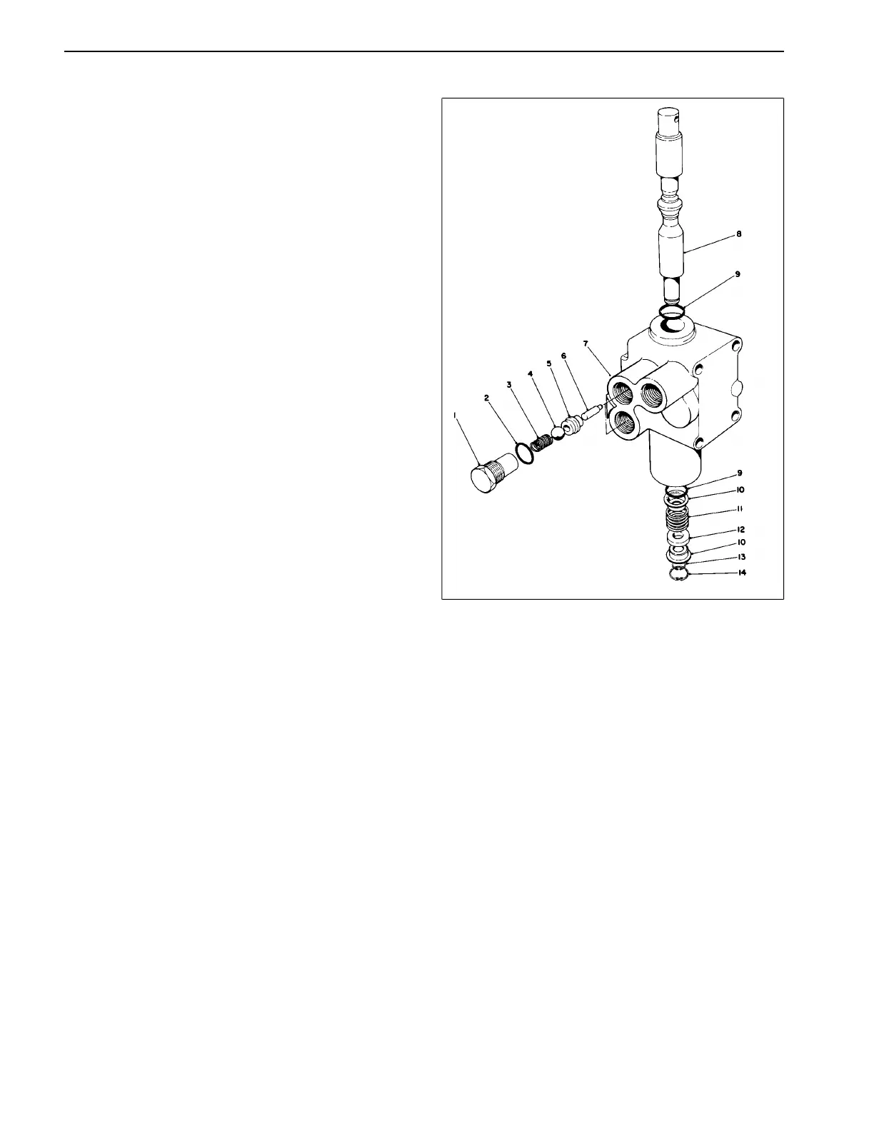
Lift Control Valve (Fig. 44)
1. After removing control valve from machine, wash
valve in solvent and dry it thoroughly.
2. Carefully mount control valve into a vise so that
control valve mounting pads are against jaws of vise.
The control valve spool snap ring (Item 14) should be
facing up.
3. Remove plug (Item 1) from side of valve body. Inside
the valve body, under the plug, there is a spring (Item 3),
ball (Item 4), and cam pin (Item 6); remove these parts.
4. Repeat step 3 for the other plug.
5. Remove snap ring (Item 14) located in bottom of valve
body. This snap ring retains spool centering spring
assembly. Remove spool snap ring (Item 13), spring
retainer (Item 10), spacer (Item 12), and spring
(Item 11).
6. Carefully push and twist control valve spool to remove
it from valve body. Set spool assembly aside.
7. Use a hooked scribe or thin screwdriver to remove
O-rings (Item 9) from inside bore of valve body (be
careful not to scratch valve bore finish).
8. Inspect all components of control valve assembly for
wear, paying special attention to valve spool. Signs of
wear on one side of spool may indicate a bent spool.
Inspect spool for flatness, and replace it if necessary.
9. Wash parts in solvent. Dry parts with compressed air.
Do not wipe them dry with a cloth or paper as lint and
dirt may remain.
10. Prior to reassembly, coat all O-rings with oil. Install
spool into valve body before inserting cam pin (Item 6),
ball (Item 4), spring (Item 3), and hex plug (Item 1).
11. Complete reassembly by reversing these proce-
dures and installing new O-rings and seals.
Figure 44
Repairs Page 5 - 42 Reelmaster
®
216/216-D
 Loading...