HYDRAULICS & ENGINE MOUNTING
4-1
Toro 30” Aerator Service Manual
4
Hydraulics
Hydraulic Subsystem
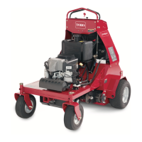
Fig. 066 subsystem hydraulic
Bottom view engine pump pulley & idler
A. Reservoir assembly E. Pump, hydraulic
B. Valve manifold with F. Belt
check & relief G. Pulley
C. Hyd cylinder assembly H. Filter
D. Gauge, pressure
Apply lm of hydraulic oil to hydraulic oil gasket
prior to installation.
Apply Loctite
®
(202) to set screws. Torque to 105
+ 10 in-lbs. (12 + 1 Nm)
3
4
Pump to be oriented so that the body is offset to
the outside of the unit.
Bottom of hub to be ush with bottom of pump
shaft
Idler to be pushed into belt hand-tight (minimum
15 lbs. or 6.6kg) when fastener is tightened.
Hydraulic oil ll level to be between “COLD”
bafe and down a 1/4” below. Check with the
aerator tines down (resting on the ground) and
uid temperature at 71
o
+ 10
o
F (21.6 + 6.6
o
C).
5
6
7
10
(Fig. 066)
See engine “Hydraulic Pump Belt Removal and
Installation” as shown in this chapter.
A
BD
C
E
F
G
10
3
6
7
4
5

 Loading...