Groundsmaster 4100--D/4110--D Page 5 -- 25 Electrical System
Cutting Deck Lift Switches
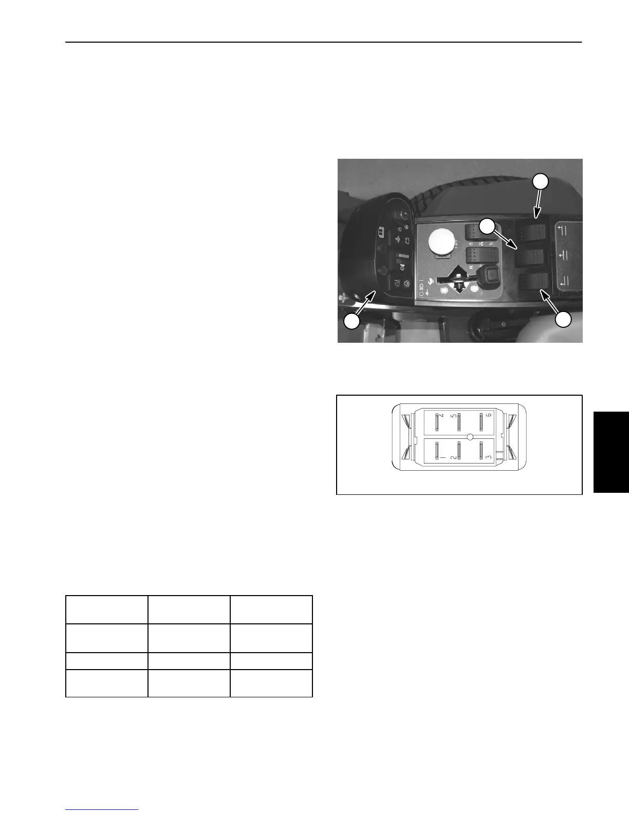
The cutting deck lift switches are used as inputs for the
TEC--5001 controller to raise or lower the cutting deck
sections.W henthefrontofaliftswitchisdepressedand
held, the controlled deck will lower. When the rear of a
liftswitchisdepressedandheld,thecontrolleddeckwill
raise. The deck section will remain in position when the
switch is released. The lift switches are located on the
console arm (Fig. 26).
NOTE: To lower the cutting deck (or wing decks), trac-
tion speed has to be in low range (4WD). Also, to raise
orlowerthe deck, theoperatorseathas to beoccupied.
Testing
1. Before disconnecting the lift switch for testing, the
switch and its circuit wiring should be tested as a
TEC--5001 input with the Diagnostic Display (see Diag-
nostic Display in the Troubleshooting section of this
chapter). If the Diagnostic Display verifies that the lift
switchandcircuitwiringarefunctioningcorrectly,nofur-
therswitchtestingisnecessary.If,however,theDisplay
determines that the lift s witch and circuit wiring are not
functioning correctly, proceed with test.
2. Make sure ignition switch is OFF. Remove key from
ignition switch.
3. Disassemble console arm to gain access to cutting
deck liftswitches (see Console Arm Disassembly in the
Service and Repairs section of Chapter 7 -- Chassis).
4. Disconnect harness electrical connector fromthe lift
switch.
5. The switchterminalsare markedasshown inFigure
27. The circuit logic of the lift switches is shown in the
chartbelow.Withtheuseofamultimeter(ohmssetting),
theswitchfunctionsmaybetestedtodeterminewhether
continuityexists betweenthe variousterminalsforeach
position.Verifycontinuitybetweenswitchterminals.Re-
place switch if testing identifies a faulty switch.
SWITCH
POSITION
CLOSED
CIRCUITS
OPEN
CIRCUITS
DECK LOWER 2+3
5+6
2+1
5+4
NEUTRAL NONE ALL
DECK RAISE 2+1
5+4
2+3
5+6
6. Ifliftswitchtestscorrectlyandcircuitproblemstillex-
ists,checkwireharness(seeElectricalSchematicsand
Wire Harness Drawings in Chapter 10 -- Foldout Draw-
ings).
7. After testing is completed, connect wire harness
connector to the lift switch.
8. Assembleconsolearm(seeConsoleArmAssembly
inthe Serviceand Repairssectionof Chapter7 -- Chas-
sis).
1. Console arm
2. Front deck lift switch
3. RH deck lift switch
4. LH deck lift switch
Figure 26
1
2
3
4
Figure 27
BACK OF SWITCH
NOTE: Lift switch terminals 4, 5 and 6 are not used on
Groundsmaster 4100--D and 4110--D machines.
Electrical
System
 Loading...


