DisassemblingtheBodyAssembly(continued)
g289456
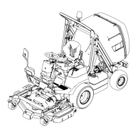
Figure148
1.Control-leverknob3.Screw
2.Console-right
12.Removetheknobsandcontrolleversfromtheauxiliarycontrolvalve(item
1inFigure148).
13.Removethe2screws(item3inFigure148)thatsecuretherightconsole
tothefairing.
14.Lifttherightconsoleandsetaside.
AssemblingtheBodyAssembly
1.Ifremoved,installtherightconsoleontothefairingandsecurewiththe2
screws(Figure148.)
2.Installthecontrolleversandknobsontotheauxiliarycontrolvalve.
3.Ifremoved,installtheleftconsoleontothefairingandsecurewiththe3
screw(Figure147).Installthethrottleleverknob.
4.Ifremoved,installthesteeringcolumncoversusingtheFigure146asaguide.
5.Connecttheelectricalwireharnessconnectorstothecenterdashboard.
6.Installthedashboardtothesteeringcolumnandsecureitwiththescrews.
7.Installtheshaftkeyintothesteeringcontrolvalve.
8.Installthebushing(8)ontothesteeringcontrolvalveandsecurewiththe
washer(6)andsocketheadscrew(5).
9.Installthewasher(2)andsteeringwheel(1)ontothesteeringcolumnand
securewithanewpin(7).
ProLineH800
Page7–7
Chassis:ServiceandRepairs
19241SLRevB
 Loading...


