Maintenance
53
m–3744
1
2
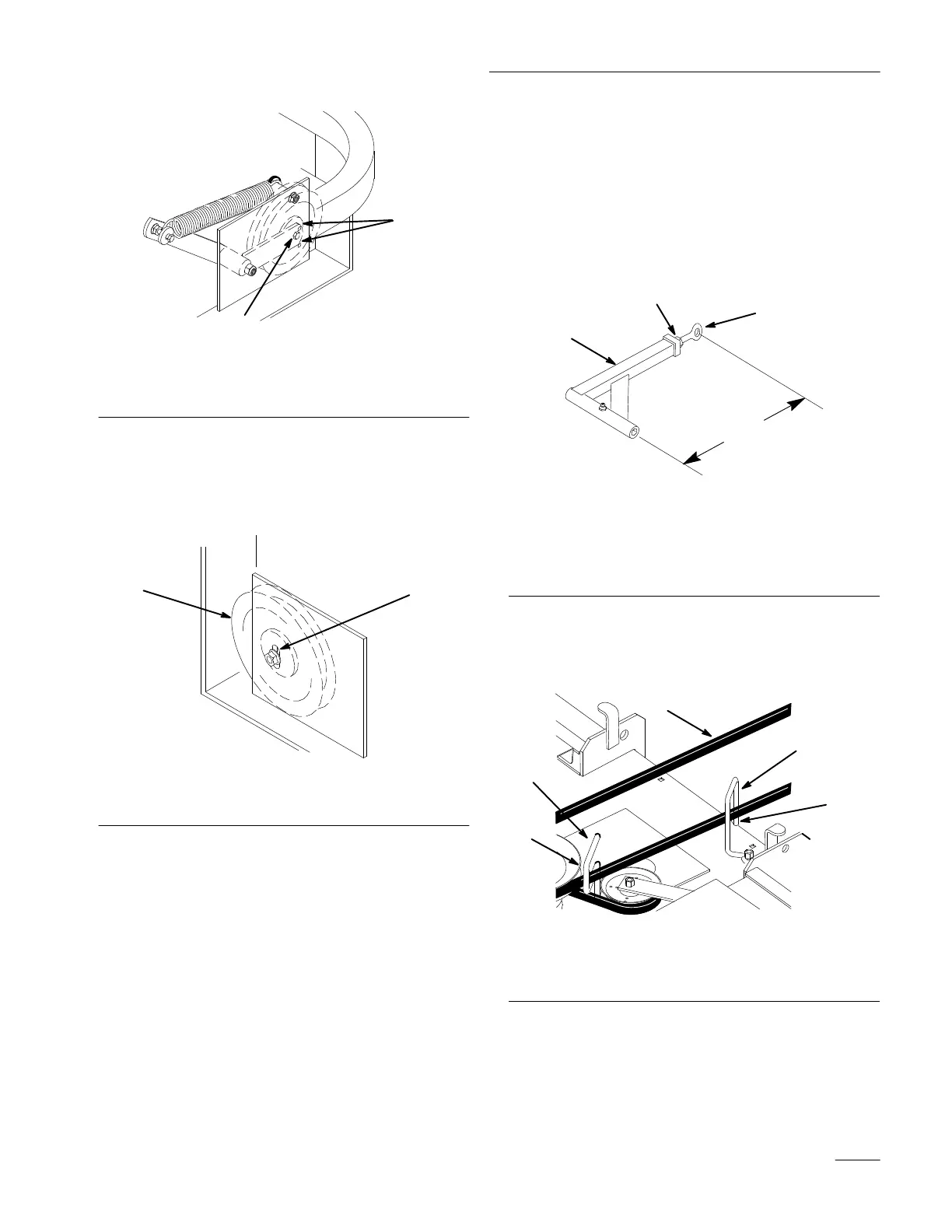
Figure 47
1. Center
bolt, spring loaded
idler
2.
Alignment hole
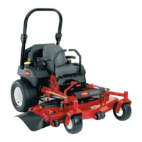
7. If adjustment is required, loosen the fixed idler
on right support plate and move up or down in
adjustment slot. To relieve belt tension lift up on
spring loaded idler.
m–3746
12
Figure 48
1. Fixed
Idler
2.
Adjustment slot
8. Check belt tension again. The center bolt of
spring loaded idler must be between the two
alignment holes in left support plate (Fig 47).
Adjust, if necessary, and tighten all hardware
securely.
9. If the fixed idler contacts the end of the
adjustment slot and more belt tension is
required, a small change in the lengthen the push
arms can be made (Fig. 49).
10. To lengthen, loosen jam nut and rotate ball joint
counterclockwise, one turn at a time. Adjust
each side the same amount.
m–3740
1
3
2
1
Figure 49
1. Push
arm
2.
15” (381 mm) nominal
3.
Jam nut
4.
Ball joint
11. Rotate the belt guide, on rear of the mower, so it
is 1/8”–1/4” (3–7 mm) away from the vertical
side of the PTO belt (Fig. 50).
1
2
3
1
3
Figure 50
1. Belt
guide
2. PT
O Drive belt
3.
1/8”–1/4” (3–7 mm)