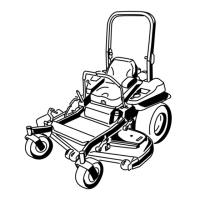
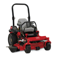
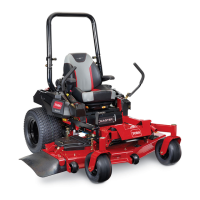
ProductOverview
Figure4
1.Side-dischargedeector
8.Rear-shockassembly
2.Height-of-cutdeck-lift
pedal
9.Seatbelt
3.Parking-brakelever10.Fuelcap
4.Transportlock11.Mowerdeck
5.Controls12.Casterwheel
6.Motion-controllevers13.Front-shockassembly
7.Rollbar
Controls
Becomefamiliarwithallthecontrolsbeforeyoustartthe
engineandoperatethemachine(Figure4andFigure5).
g0131 12
1
2
3
4
5
6
25
25
10
15
C
H
ECK
ENG
IN
E
Figure5
1.PTOSwitch
4.Hour
meter/Safety-interlock
display/Fuelgauge
2.Throttlecontrol5.Ignitionswitch
3.Malfunction-indicatorlight
(MIL)
6.Fuses
FuelGauge
Thefuelgaugeislocatedwiththehourmeter,andthebars
lightupwhentheignitionswitchison(Figure6).
Theindicatorlightappearswhenthefuellevelis
low—approximately3.8L(1USgallon)remaininginthe
fueltank.
Figure6
1.Fuelgauge(bars)4.Safety-interlocksymbols
2.Batterylight
5.Low-fuelindicatorlight
3.Hourmeter
HourMeter
Thehourmeterrecordsthenumberofhourstheenginehas
operated.Itoperateswhentheengineisrunning.Usethese
timesforschedulingregularmaintenance(Figure6).
Safety-InterlockIndicators
Therearesymbolsonthehourmeterandtheyindicatewitha
blacktrianglethattheinterlockcomponentisinthecorrect
position(Figure6).
Battery-IndicatorLight
WhenyouinitiallyturntheignitionkeytotheRUNposition
forafewseconds,thebatteryvoltagedisplaysinthearea
wherethehoursarenormallydisplayed.
Thebatterylightturnsonwhentheignitionisturnedonand
whenthechargeisbelowthecorrectoperatinglevel(Figure
5).
ThrottleControl
ThethrottlecontrolisvariablebetweentheFASTandSLOW
positions.
14
 Loading...