ProductOverview
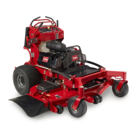
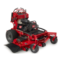
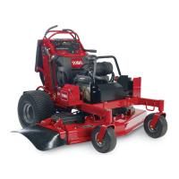
Figure4
1.Frontcasterwheel7.Fueltank
2.Side-dischargechute8.Platform(downposition)
3.Engine
9.Fuel-shutoffvalve
4.Controls
10.Battery
5.Controllevers
11.Mowerdeck
6.Hydraulictank
Controls
Becomefamiliarwithallthecontrols(Figure5)beforeyou
starttheengineandoperatethemachine.
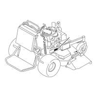
Figure5
1.Fuelcap
8.Height-of-cutlever
2.Choke9.Height-of-cutpin
3.Parking-brakelever
10.Platformlatch
4.Hydraulic-tankcap11.Rightmotion-controllever
5.Hourmeter12.Blade-controlswitch
(PTO)
6.Ignitionswitch
13.Leftmotion-controllever
7.Throttlecontrol
HourMeter
Thehourmeterrecordsthenumberofhourstheenginehas
operated.Itoperateswhentheengineisrunning.Usethese
timesforschedulingregularmaintenance(Figure5).
Safety-InterlockIndicators
Symbolsonthehourmeterindicatewithablacktrianglethat
theinterlockcomponentisinthecorrectposition(Figure5).
Battery-IndicatorLight
IftheignitionkeyisturnedtotheONpositionforafew
seconds,thebatteryvoltagedisplaysintheareawherethe
hoursarenormallydisplayed.
Thebatterylightturnsonwhentheignitionisturnedonand
whenthechargeisbelowthecorrectoperatinglevel(Figure
5).
ThrottleControl
ThethrottlecontrolisvariablebetweentheFASTandSLOW
positions(Figure5).
12

 Loading...
