HYDRAULIC DRIVE SYSTEM
6-26 Toro GrandStand Service Manual
6
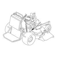
16. Lift the tower assembly up and lower it onto the
frame, taking care that the lift bar is routed between
the right hand lift cylinder and the RH Lift Rod as-
sembly. Also ensure the top end of the brake rod is
routed under the control panel and up to the brake
handle lever (Fig. 0997).
Fig. 0997 IMG-9513a
17. Align the tower and frame mounting holes. Install 4
self-tapping screws to secure the tower to the frame
(Fig. 0998).
Fig. 0998 IMG-9516a
14. 2010 only: Secure the shifter link to the shifter
bracket with a bolt two washers and nut (Fig. 0995).
Fig. 0995 IMG-0904a
15. Install a cable tie securing the wire harness and 2
low pressure hydraulic hoses (Fig. 0996).
Fig. 0996 IMG-9501a
 Loading...


