HYDRAULIC DRIVE SYSTEM
6-49Toro GrandStand Service Manual
6
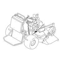
3. Install 2 carriage bolts, nuts and washers securing
the pump to the frame (Fig. 1080).
Fig. 1080 IMG-9457a
4. Install the hoses to the ttings located on the pump.
Ensure the markings on the hoses match the mark-
ings on the ttings and pump:
a. Install the high pressure hoses (Fig. 1081).
Fig. 1081 IMG-9451a
b. Install the charge line and secure with the hose
clamp (Fig. 1082).
Fig. 1082 IMG-9446a
c. Install the return line and secure with the hose
clamp (Fig. 1083).
Fig. 1083 IMG-9443a

 Loading...


