RemovingtheRotorAssembly(continued)
Note:Therotorassemblycomponentsarenotavailableseparately.Ifrotor
damageoccurs,replacethecompleterotorassembly.
InstallingtheRotorAssembly
RefertoFigure40fortheforthisprocedure.
Note:Washers(item10)areusedtopreventtherotorfromcontactingthe
rotorhousingassembly.Typically,2washersarenecessary.
1.Installthesamenumberofwasherspreviouslyremovedfromtherotorshaft.
2.Positionthewoodruffkeyintheslotintherotorshaft.Slidetherotorassembly
andspacerontotherotorshaft.Ensurethattherotordoesnotcontactthe
innerrotorhousing.Ifnecessary,addanadditionalwashertogainclearance.
3.Slideanewinnertabwasher(largerouterdiameter)andthentheoutertab
washerontotherotorshaft.
IMPORTANT
Thenutusedtosecuretherotorassemblytotherotorshafthas
left-handthreads.Tightenthenutbyrotatingitcounterclockwise.
4.Usethe1-1/4inchatsprovidedtoholdtherotorshaftandinstallthehexnut
(item4).Useanoffsetwrenchtotightenthehexnutfrom258to284N∙m
(190to210ft-lb);refertoOffsetWrench(page2–13).
5.Lockthehexnutinpositionbybendingtheinnertabwasherovertheouter
tabwasherandoneofthehexnutats.
g280194
Figure41
1.Hexnut
2.Innertabwasher(foldover)
6.Installthefrontcap(item3),wavewasher,andretainingringontotheshaft.
7.Installtheblowerdriveshaft;refertoInstallingtheBlowerDriveShaft(page
6–5).
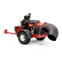
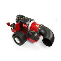
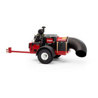
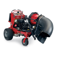
ProForce®DebrisBlower
Page6–9
BlowerAssembly:ServiceandRepairs
18237SLRevA
 Loading...