RemovingtheRotorShaft(continued)
7.Inspecttherotorshaft,bearingboresofthebearingcaps,andbearingsfor
wearordamage,andreplacethepartsasnecessary.
InstallingtheRotorShaft
RefertoFigure42forthisprocedure.
1.Installtheinnerretainingringsintotherotorshaftgroovesiftheywere
removed.
2.Installthebearingsontotherotorshaftbypressingontheinnerraceofthe
bearing.Ensurethatthebearingsareseatedagainsttheinnerretainingrings.
3.Installtheouterretainingringsintotherotorshaftgrooves.
4.InstallanewO-ringintotherearbearingcap.Applyathinlmofoiltothe
O-ring.
5.Applymediumstrengththreadlockingcompoundto4oftheange-head
screws(item1)andsecurethecenterplateandrearbearingcaptotheinner
housing.Tightenthescrewsfrom10.2to11.3N∙m(90to100in-lb).
6.Positiontheendcap(item4)betweenthebearingsoftherotorshaft
assembly.
7.Alignthetabontheendcapwiththeslotintheinnerhousingandinstallthe
rotorshaftassembly.Ensurethatthebearingsareseatedinthebearingcaps
andthefrontbearingcapisseatedintheinnerhousing.
8.Applymediumstrengththreadlockingcompoundto4oftheange-head
screws(item1)andsecuretheendcapandfrontbearingcaptotheinner
housing.Tightenthescrewsfrom10.2to11.3N∙m(90to100in-lb).
9.Ensurethattherotorshaftrotatesfreely,andcorrectanyissuesbefore
proceeding.
10.Installthenozzleandthenozzleclamp.Positionthenozzleclampfasteners
attheseaminsidethenozzleandtightenfrom4.5to5.5N·m(40to50in-lb).
11.Installtherotorassembly;refertoInstallingtheRotorAssembly(page6–9).
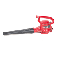
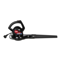
ProForce®DebrisBlower
Page6–11
BlowerAssembly:ServiceandRepairs
18237SLRevA

 Loading...