Reelmaster 6500–D/6700–D
Page 4 – 49
Hydraulic System
Wheel Motor
T–2117
1
2
3
4
5
6
7
8
9
10
16
17
18
19
11
12
13
14
15
4
5
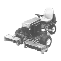
Figure 28
1. Retaining Ring 8. HH Screw 15. Valve Plate
2. Shaft Seal 9. Backplate Assembly 16. Rotating Kit
3. Washer 10. O–Ring 17. Camplate Insert
4. Retaining Ring 11. Speed Pickup Sensor 18. Housing
5. Thrust Race 12. Dowel Pin 19. Needle Bearing
6. Thrust Bearing 13. Dowel Pin
7. Splined Drive Shaft 14. Needle Bearing
Cleanliness is extremely important when repairing
these motors. Work in a clean area. Before disconnect-
ing the lines, clean port area of motor. Disconnect hy-
draulic lines, removing motor assembly from vehicle
and plug ports. Thoroughly clean the outside of the mo-
tor. After cleaning, remove port plugs and drain oil.
Tools Required for Disassembly and Reassembly
1/2 in. Socket
Ratchet Wrench
Torque Wrench, 68 Nm [50 Ibs. ft.]
Soft Face Hammer
Internal Retaining Ring Pliers
(Straight 2.3mm[.090 in.] Tip)
External Retaining Ring Pliers
(Straight 1.8mm[.070 in.] Tip)
Seal Driver or Similar Tool
Petroleum Jelly (Such as Vaseline)
Disassembly
1. Clamp the drive shaft end of the piston motor in a pro-
tected jaw vise with the cap screws up. Remove the six
cap screws (8) from the motor assembly.
2. Use a mallet and tap the backplate (9) to loosen and
remove from housing.
3. Remove valve plate (15) and O–ring (10) from back-
plate. It is not necessary to remove roll pins in backplate.
4. Remove motor from vise and remove rotating assem-
bly (16) from motor housing.
5. Remove the camplate insert (17) from housing (18).
Use caution not to mar the finish that makes contact with
pistons.
6. Remove retaining ring (1) from housing. Press shaft
(7) from housing (18) and remove shaft seal (2), and
washer (3).
Hydraulic
System

 Loading...