Reelmaster 6500–D/6700–DPage 7 – 10Cutting Units Rev. B
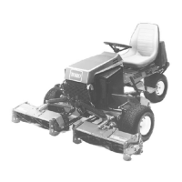
Model 03853
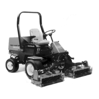
Model 03854
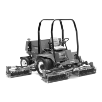
Model 03855
Height of Cut
The Height–of–Cut adjustment is made by moving the
rear roller up or down, after adjusting and leveling the
front roller. This can be done by using the adjusting
screw or quick height–of–cut locating pin (Fig. 13 & 13).
Note: To ensure accuracy, initial rear roller set–up
should be performed on a leveling plate .
1. Select proper rear roller position holes for desired
height–of–cut (Fig. 13 & 15).
Note: If final height–of–cut settings other than those
shown in figure 15 are desired, select the set of position
holes closest to desired height–of–cut. Use top cap-
screws (Fig. 13) to adjust to final setting.
2. Position cutting unit on a flat level surface (leveling
plate).
3. Depending on which front roller position is selected,
adjust capscrew on top of each rear roller bracket to at-
tain approximate distance (Dimension X) between sup-
port and bracket (Fig. 13 & 13).
4. Continue to adjust top capscrews slightly to level rear
roller if required.
5. Tighten retainer nut securing roller bracket to angle
bracket.
6. Verify desired height–of–cut using gauge bar.
Note: Once cutting unit has been properly set–up (lev-
eled and parallel), height–of–cut can be quickly
changed by changing the quick height–of–cut pin loca-
tion.
Figures 13 & 15 show the height–of–cut settings which
can be achieved by installing the the quick height–of–
cut pin in the different hole combinations.
Figure 13
X
2
4
1. Height–of–cut adjusting capscrew
2. Height–of–cut support
3. Quick height–of–cut pin
A
B
5
A
B
C
C
1
3
Front Roller Position
Rear Bracket Distance (X)
4. Roller bracket
5. Front roller
6. Angle bracket
6
Figure 14
Front Roller Position
(Dimension X, Fig. 13)
A 15/16” (24mm)
B 5/8” (16mm)
C 1/2” (13mm)
Distance between brackets
1 2 34 5 6
3/8” XX
1/2” XX
5/8” XX
3/4” XX
7/8” XX
1” XX
1–1/8” XX
1–1/4” X X
Height
–of–Cut
Height–of–Cut
Hole In Support
Side Plate Hole
Upper Lower
REAR ROLLER POSITIONS
Figure 15
(9mm)
(13mm)
(16mm)
(19mm)
(22mm)
(25mm)(25mm)
(28mm)
(31mm)

 Loading...


