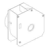
Figure4
1.Supportbracket2.Selftappingscrews(5/16
x3/4inch)
3.Removethefastenerssecuringtheexisting
rectangularspacerplatefromthetopoftheengine
frameandremovetheplate,ifsoequipped.
4.Installthenewanglespacerplateasshown
in
Figure5usingthefastenersremovedpreviously.
5.Installthebaggerframetothesupportbracket.
Securethebaggerframewithaclevispin(1/2x
2-1/4inch)andhairpincotter(
Figure5).
Figure5
1.Baggerframe5.Clevispin(1/2x2-1/4
inch)
2.Existingrectangular
spacerplate(ifso
equipped)
6.Spacerplate,angle(new)
3.Hairpin7.Fasteners,existing
4.Supportbracket
6.Installtwosupportrods,onetoeachsideofthe
baggerframe.Locatetheexistingbracketbetween
thereardrivewheelandframe(
Figure6).
Figure6
Leftsideshown
1.Baggerframe
4.Hairpin
2.Clevisend5.Bracketonframe
3.Clevispin
6.Washer
7.Insertthebentendsoftherodintothebaggerframe
asshowninFigure6.Securetheendoftherodwith
awasherandhairpin.
8.Adjustthesupportrodssothatbaggerframeisheld
securetothemachineframeandseatsinthenotch
oftheanglespacerplateinstalledpreviously.Repeat
thesestepsforeachsupportrod:
A.Loosenthejamnutatthebaseoftheclevisend
oftherod.
B.Rotatetheclevisendoftherodtoadjusttherod
tothedesiredlength.
C.Aligntheholesintheclevisendwiththeholein
thebaggerframeattheattachmentpoint.
D.Securetheclevisendoftherodstothebagger
frameusingaclevispinandhairpincotter
(
Figure6).
E.Tightenthejamnut.
9.Withbothrodsinstalledandattached,checkthe
baggerframeforplay.Thebaggerframeshouldbe
heldtighttothemachineframe.Ifnecessary,repeat
theprevioussteptosecurethebaggerframe.
5
 Loading...