ELECTRICAL ADJUSTMENTS
D-4
2-18: LEVEL
1.
2.
3.
Connect the AC voltmeter to pin 6 of CP101.
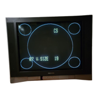
Activate the adjustment mode display of Fig. 1-1 and
press the channel button (33) on the remote control to
select “LEVEL”.
Press the VOL. UP/DOWN button on the remote control
until the AC voltmeter is 85 ± 2mV.
Please check if the fixed values of the each adjustment
items are set correctly referring below.
2-19: Confirmation of Fixed Value (Step No.)
FUNCTION
H.VCO
AFC GAIN
V.SHIFT
VS CORRECTION
BRI.MAX
BRI.MIN
CONT.CENT
CONT.MIN
COL.MAX
COL.MIN
SHARPNESS
CB DL
CR DL
NO.
02
04
05
09
15
17
19
20
21
23
25
26
27
RF
04
04
02
42
140
50
64
20
90
00
40
00
00
CS
04
04
02
42
140
50
64
20
90
00
40
00
00
AV
04
04
02
42
140
50
64
20
90
00
40
00
00
 Loading...