85
4400 Series Installation and Operation Manual – 64527-008
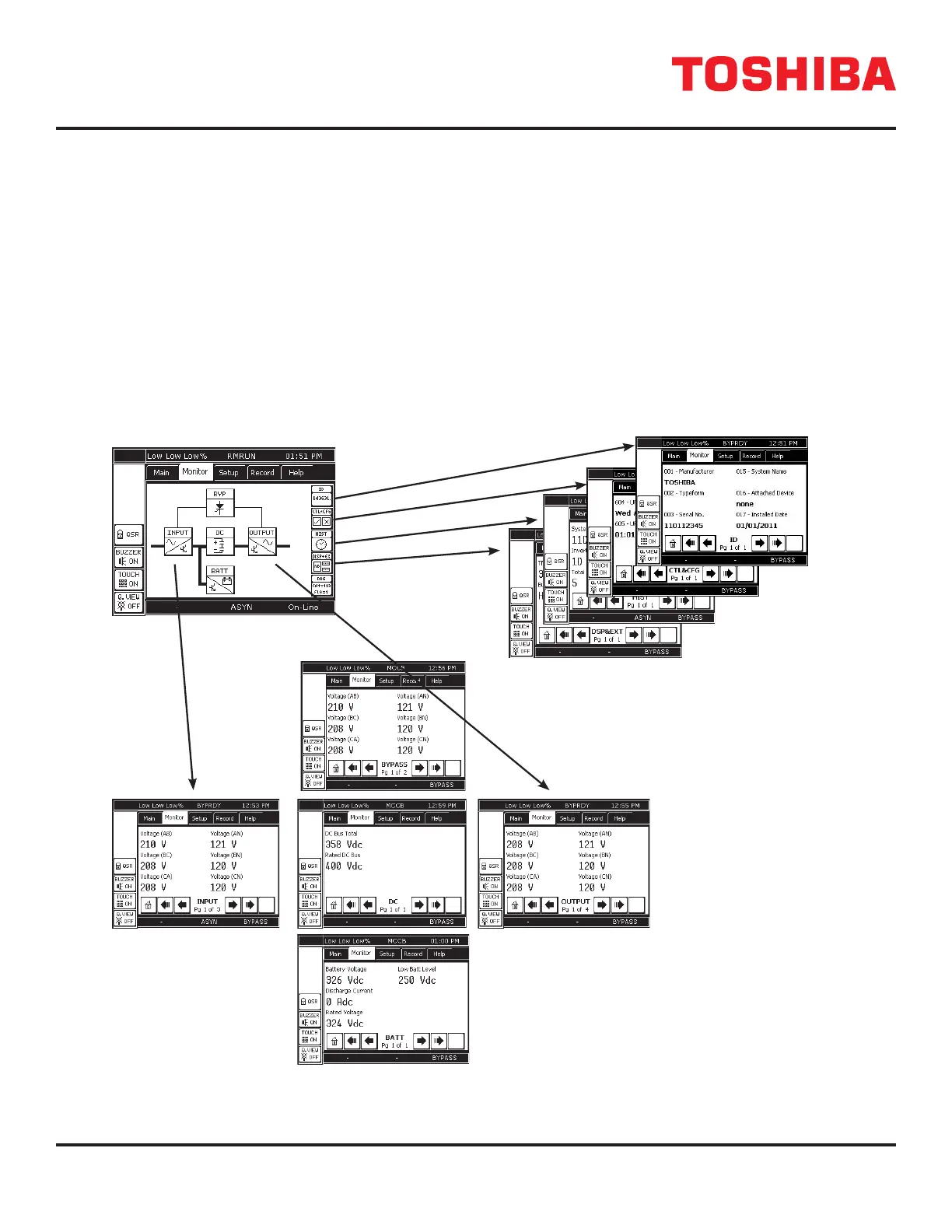
12.15 Tab: Monitor
The MONITOR tab allows the user to select a specic group of performance parameters to view; Input, Output, Bypass,
DC Link, ID, Control and Conguration, History, and Display and External Communications (RemotEye).
The right side of the display is a vertical stack of ve buttons: 4 active and 1 reserved for future use.
The middle of the display contains ve buttons arranged in a diagram representing the functional model of the UPS. The
lines connecting the mimic buttons represent the power ow from input to output. A thin line indicates no current ow, and
a thick or bold line indicates current ow. See the Mimic Display current Flow Indicator illustration on the following page.
The gure below illustrates the data displayed when the corresponding button is pressed.
MONITOR TAB
FIGURE 12.12: MONITOR TAB DISPLAY OPTIONS
4400F3F050
4400F Series UPS
 Loading...