14 / 73
Copyright © 2019 Toshiba Teli Corporation, All Rights Reserved. http://www.toshiba-teli.co.jp/en/
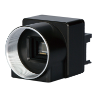
Connector Pin Assignment
● Video output / Controlling / Power supply connector (CameraLink Base Configuration)
- Connector type : HDR-EC26FYTG2+ (Manufactured by Honda Connectors)
*When connecting a cable to the camera, please turn off the power supply firstly.
*CC2+, CC2-, CC3+, CC3-, CC4+, CC4- : Not used
- Bit assignment of camera output
*When connecting a cable to the camera, please turn off the power supply firstly.
*The allocation of the port conforms to the CameraLink standard.
 Loading...