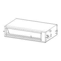
E-box
[04]
Refrigerant pipe Drain pipe
[01][03]
No.
16
Item
Louver control:
In case of 4-way
Cassette type
and ceiling type
Outline of specifications
1) Louver position setup
• When the louver position is changed, the position moves
necessarily to downward discharge position once to return
to the set position.
• The louver position can be set up in the following operation
range.
In cooling/dry operation In heating/fan operation
• In group twin/triple operation, the louver positions can be
set up collectively or individually.
In case that HEAT refrigerant recovery control was
performed in STOP status, the louver position becomes
horizontal when the operation is resumed.
2) Swing setup
• [SWING] is displayed and the following display is repeated.
In all operations
• In group operation, the louver positions can be set up
collectively or individually.
3) When the unit stopped or the warning was output, the louver
is automatically set to full closed position.
4) When PRE-HEAT
(Heating ready) is displayed
(Heating operation started or defrost operation is performed),
heating thermo is off or self-cleaning is performed, the louver is
automatically set to horizontal discharge position.
* The louver which air direction is individually set or the locked
louver closes fully when the unit stops and the louver is
automatically set to horizontal discharge position when PRE-
HEAT
(Heating ready) is displayed, heating thermo is off.
• For the air direction illustration during normal operation, the
air direction of the least No. among the louvers
which are block-set is displayed.
• While individual air direction is being set,
the remote controller operation
(Illustration of air direction) and operation
of the real machine are linked.
• When selecting a case,
UNIT LOUVER
Louver
select button is not pushed or louver No.
is not displayed, the air directions of all
the louvers are ollectively set up.
Remarks
The louver position at
horizontal discharge position
at under AP030 differs from
that at over AP036.
The swinging louver moves
usually up to the ceiling side
from the louver position of
the set time.
Setup from the remote
controller without
UNIT LOUVER
button is unavailable.
For the setup operation,
refer to “How to set up
louver individually” of Item
“Setup at local site/Others”.
Using same as the present
4-way Air Cassette Type is
possible
In Case of
4-way cassette
type only
<<Individual air direction setup>>
• Pushing
UNIT LOUVER
Louver select button enables every discharge
port to set up the air direction.
The louver numbers that are displayed on the display part
correspond to those in the following figure.
• In case of no input (key operation) for approx. 5 seconds
during setting of individual air direction (during displaying of
louver No. on the remote controller screen), the remote
controller screen returns to the normal display screen.
 Loading...