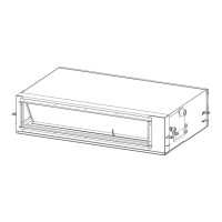
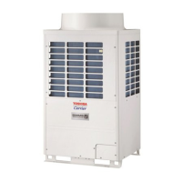
Valve fixing plate
Inverter assembly Side cabinet
Fin guard
Inverter protective cover
Partition boardMotor base
Heat exchanger Discharge
port cabinet
No.
d
e
Part name
Discharge
port cabinet
Side cabinet
Procedure
1. Detachment
1) Perform work of Detachment 1 of
c
.
2) Remove screws for the discharge port
cabinet and the partition board.
(M4, 8 mm, 4 pcs.)
3) Remove screws for the discharge port
cabinet and the bottom plate.
(Hexagonal screw M4, 10 mm, 2 pcs.)
4) Remove screws for the discharge cabinet
and the motor base. (M4, 8 mm, 2 pcs.)
5) Remove screw for the discharge cabinet
and the heat exchanger. (M4, 8 mm, 1 pc.)
6) Remove screws for the discharge port
cabinet and the fin guard.
(Hexagonal screw M4, 10 mm, 2 pcs.)
1) Perform work of Detachment 1 of
c
.
2) Remove the screws which fix the inverter
assembly and the side cabinet.
(M4, 8 mm, 2 pcs.)
3) Take off screws that fix the wiring division
panel and the side cabinet.
4) Remove the screws for the side cabinet
and the valve fixing plate.
(M4, 8 mm, 2 pcs.)
6) Remove screws for the side cabinet and
the piping panel (Rear).
(Hexagonal screw M4, 10 mm, 2 pcs.)
6) Remove screw for the side cabinet and the
bottom plate.
(Hexagonal screw M4, 10 mm, 1 pc.)
7) Remove screws for the side cabinet and
the fin guard (Heat exchanger).
(Hexagonal screw M4, 10 mm, 5 pcs.)
Remarks
f
Inverter
protective
cover
1) Perform work of Detachment 1 of
c
.
2) Take off screw which fixes the inverter
assembly and the inverter protective cover.
(M4, 8 mm, 1 pc.)
 Loading...
