e-STUDIO555/655/755/855 © 2009 - 2011 TOSHIBA TEC CORPORATION All rights reserved
LASER OPTICAL UNIT
7 - 12
7.6 Disassembly and Replacement
[A] Laser unit cooling fan
(1) Take off the top right cover, right upper cover,
right center cover and right rear cover.
( P.2-42 "[C] Top right cover",
P.2-43 "[F] Right upper cover",
P.2-43 "[G] Right center cover",
P.2-43 "[H] Right rear cover")
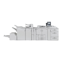
(2) Remove 1 screw, loosen 9 screws and take
off the plate cover.
Fig. 7-13
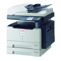
(3) Remove 1 screw fixing the Laser unit.
(Not reguired for e-STUDIO755/855)
(4) Remove 2 screws and take off the laser unit
fixing stay.
Fig. 7-14
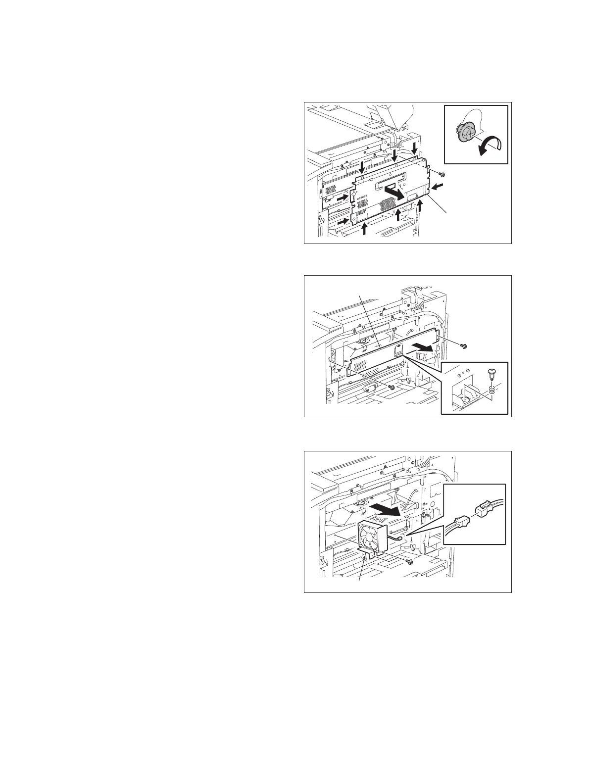
(5) Disconnect 1 connector and remove 2
screws to take off the laser unit cooling fan.
Fig. 7-15
Plate cover
Laser unit fixing stay
Laser unit cooling fan

 Loading...