3. Connectivity
DANGER
!
Contact
With
Energized
Wiring
Will
Cause
Severe
Injury
Or
Loss
Of
Life.
W hen using an ASD output disconnect, the ASD and the motor
MUST
be stopped before the
disconnect is either opened or closed. Closing the output disconnect while the 3-phase output
of the ASD is active may result in equipment damage or injury to personnel.
De-energize and lockout/
tagout the main power,
control power, and
instrumentation
connections
before
connecting or
disconnecting the power
wiring to the equipment or
openin g the enclosure
door.
Connect the 3-phase input
power to the ASD to
terminals
R/L1
,
S/L2
, and
T/L3
. Connect the 3-phase outpu t power from
term inals
U/T1
,
V /T2
, an d
W/T3
to the
m o tor. Ens ure that all wiring is performed in accordance
with
national, state, and local electrical codes.
Install a circuit disconnecting device and brand circuit protection in accordance with the fault
current settings of the ASD and the 200 8 NEC Ar ticle 430.
The default settings of the ASD require the use of a factory-installed jumper from
the
CC
to
ST
terminals t o e nable the ASD.
For
2-W ire Control
and
3-Wire Control
open the enclosure
door to gain access to the
Terminal
Board
and continue below.
2-Wire Control
Insta ll
a switch as described below from the
F
and/or
R
terminals to the
CC
terminals. Close or
reattach t he enclosure door.
1 — Normally
open
switch that will be used to provide the forward run command (Set to
Forward).
2 — Normally
open sw itch tha t will be used to provide the reverse run com m and (Se t to
Reverse).
3-Wire Control
Install mome ntary push bu ttons as des cribed below from the
F
and/o r
R
terminals t o the
CC
terminal. Close or reattach the enclosure door.
1 — Normally
open
momentary push button that will be used to provide the forward run
command (Set to Forward).
2
— Normally
open
m omentary push button that will be used to provide the reverse run
comman d (Set to Reverse).
3 — Norm ally
closed
m omentary pu sh bu tton that w ill be used to hold the outp ut frequency
upon termination of the run command (Set to Hold
:
F115
= 50 (Hold, N.O.)
.
Bef o re tu rning o n the AS D ensu r e tha t:
The enclosure door is closed or reattached, and secure.
Terminals
R/L1
,
S/L2
, and
T/L3
are
connected to the
input power
and
terminals
U/T1
,
V /T2
, and
W/T3
are connected to the motor
.
The 3-p hase inpu t vol tage is as specified
and
there are no shorts and all grounds are secure
.
RES
CC
F R S1 S2 S3 S4 CC ST FP +SU
1
2
3
TB3
3-Wire Start/S top Control C onnec tions
3-Phase Input/Output Connections
2-Wire St art/Stop Cont rol C onne ctions
RES
CC
F S1 S2 S3 S4 CC ST FP +SU
TB3
R
1
2
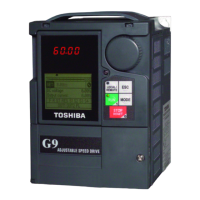
1. Rece ipt & Identification
Inspect the equipment for damage that may have occurred during
shipping.
DO NOT
install or energize equipment that has been damaged.
Ensure that the rated capacity and model number on the nameplate
conform to o rder specifications.
Use proper lifti ng t echniques when moving the G9 ASD.
Contact your Toshiba Sales Representative to report discrepancies or
for assistance if required.
TRANSISTOR INVERTER
VT130G9U4025
INPUT
OUTPUT
U (V-)
F (Hz)
I (A)
50/60
0/500
5.1
3.6
(CF 4 kHz)
3PH 380/480 3PH 380/480
G9 ASD Nameplate
2. Mounting
Only qualified personnel should install this equipment.
The installation of the equipment should conform to the 2008 National Electrical Code
(NEC)
Article 110, OSHA, as w ell as any oth er applicable nationa l, regional, o r indu stry codes and
stan dar ds.
Insta llat ion pr acti ces sh a ll conform to the latest revision of
the
NFPA 70E Electrical Safety
Requirements for Employee Wor kplace.
It is the responsibi lity of the G9 ASD installer/ mainten ance perso nne l to ensure that the un it is
insta lled in an en closure that will protect personnel against electric shock.
Location
Select a mount ing location that is easily accessible and
has adequate working space. Proper
illumina tion is required for making in spections ,
adjustments, and performing equipment
maintenance.
DO NOT
mount the G9
AS D in a location t hat would produce catastrophic results if it were to
fall from its mounting loca tion (equipment damage and/or injury to personnel).
Avoid installation in direct sunlight or in areas where vibration, heat, humidity, dust, fibers,
metal particles, explosive/corrosive m ists or gases, sources of electrical noise are presen t, or
where it would be exposed to harmful liquids, solvents, or other fluids
.
Temperature
The am bien t o pe ra t in g t e mper a t ur e rat in g is 1 4
to
104
F
(-10
to 40
C).
Ventilation
Insta ll th e unit in an upright position
and in a well-ventilated area.
W hen installin g adjacent ASDs horizontally, Toshiba recommends
at least 5 cm of space
between units. Howev er, if the top cover is removed from each ASD then horizontally
moun t ed ASDs may b e inst a lled sid e-b y- sid e wit h no space i n- bet w een th e adj a cen t A SDs
.
For 230- v olt ASDs, a m in imu m of 10 cm of space i s requ ir ed abov e an d be lo w adj a cen t A SDs
and any obstruction. For 460-volt ASDs, a minimum of 30 cm of space is required.
Lead Length
The table
below lists the recommended maximum lead lengths for the listed motor voltages.
Lead le ngths from the ASD to the motor in excess of those listed below may requ ire filters to
be added to the output of the ASD.
Excessive lead leng ths may a dverse ly affect the
performance of the mot or. Exceeding the peak voltage rating or the allowable therm al rise
time of the motor insulation will reduce the life expectancy of the motor.
Contact your Toshiba Sales Representative for application assistance when using lead lengths
in excess of those listed.
For enclosure dimensions, mounting hole dimensions, current/voltage specifications, and
cab le/termin al specifications consult the
G9 ASD Quick Start Guide
.
Model
PWM Carrier
Frequ e ncy
NE MA MG1 Part 31
Compliant Motors
2
NEMA MG1
Part 30
Compliant Motors
2
230-Volt All 1000 f eet 450 feet
460-Volt
< 5 kHz 600 feet 200 feet
>
5 kHz
300 feet 100 feet
Lead Length Recommend ations
G9 ASD Simple Start Guide
° ° °°
efesotomasyon.com -Toshiba inverter,drive,servo,plc
 Loading...