- 1027 -
5.2.1 VCT11B
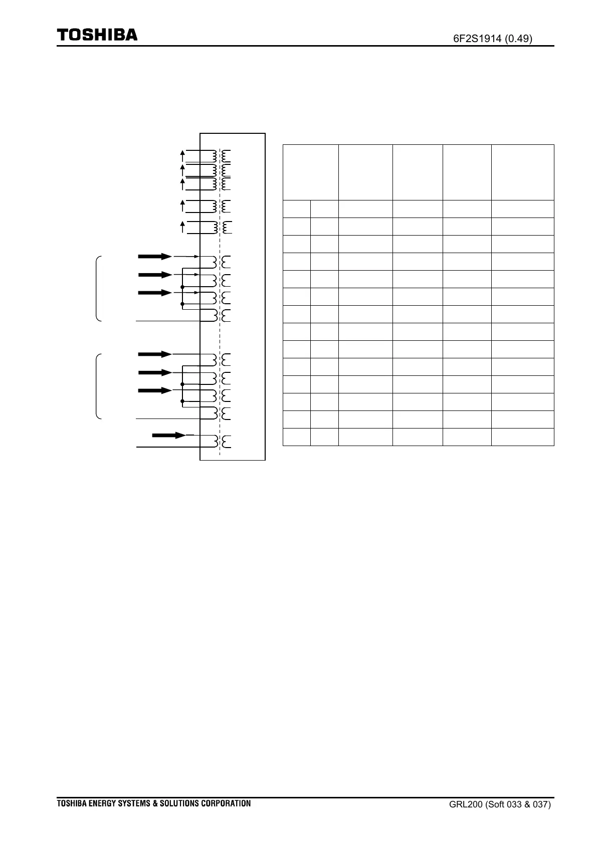
VCT11B is designed for 1.5 circuit breaker arrangement (1.5CB), as shown in Figure 5.2-3.
VCT11B is available for 1/2 size case and larger.
The three-phase currents in the
1.5CB arrangement
The other three-phase currents in the
1.5CB arrangement
The other residual current in the
parallel lines
Reference voltage on busbar
Reference voltage on busbar or
residual voltage
Figure 5.2-3 Transformer module (VCT11B)
(1)
Note: The channel number about the AC analog input is used to represent the
terminal location when the user sets the ratio about the CT or the VT. We
shall discuss later in section
Setting VCT ratio.
(2)
Note: In 5A rated operation, jumpers are inserted on all CTs, whereas no jumper is
inserted for 1A rated. To change it, see section
Changing VCT rated current
.
(3)
Note: For the destination of input signals, see Appendix:
Matrix between VCT
terminals and relay applications
.
(4)
Note: Reference voltages (Vs and Vs2) are used in the Voltage check (VCHK)
function; see Chapter
Relay applications: VCHK
.
(5)
Note: Residual voltage (Ve) can be selected when setting [APPL-Ves2] = Ve. For
more information, see the succeeding section.
AC analog
input
channel
(1)

 Loading...


