- 1086 -
5.5.3 DC voltage monitoring
(i) Threshold voltage for detection/non-detection of power error
DC voltage is monitored, and a power supply failure can be outputted from the PWS for the
Automatic supervision function. The user should set its failure level for the PWS. See
Chapter
Automatic supervision function
for more information.
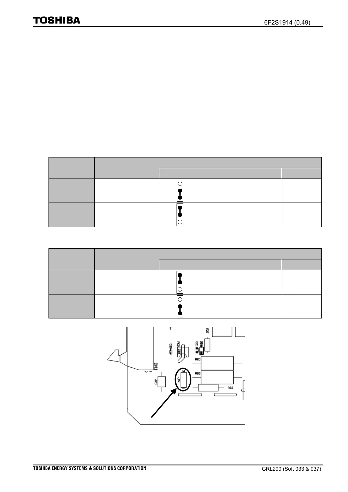
Table 5.5-5 shows the threshold voltages for detection/non-detection of the power error at the
level high and low. This also shows how to set them with a shunt connector.
Table 5.5-5 Threshold voltage for detection/non-detection of the power error
(a) In the case of DC rated voltage “110-250 Vdc”
Threshold voltage for detection/non-detection of the power error
Insert a shunt connector
to position”1-2” at JP4
Insert a shunt connector
to position”2-3” at JP4
(b) In the case of DC rated voltage “24-60 Vdc”
Threshold voltage for detection/non-detection of the power error
Insert a shunt connector
to position”2-3” at JP4
Insert a shunt connector
to position”1-2” at JP4
Figure 5.5-2 Location of JP4 on the PWS module

 Loading...


