- 1112 -
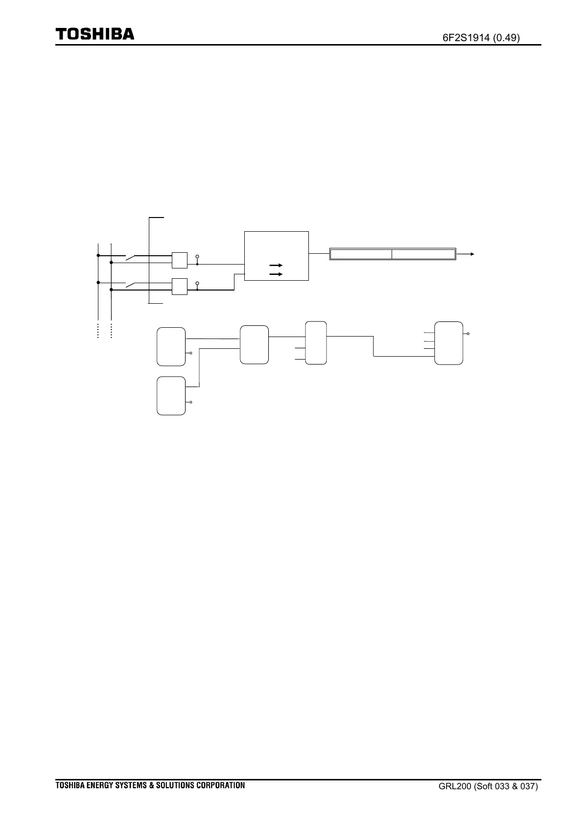
consists of a binary input circuit (BI1), a number generation function (‘Binary selection’
provided in basic functions of the PLC editor), and the signal reception point. That is, when
the B1 switch is closed, a signal enters the BI1 circuit and is carried to the Binary selection;
accordingly the Binary selection, which is programmed to generate a group number ‘2’ in UNIT
when signal ‘1’ is injected in BOOL(BIT), can generates and inject the group number ‘2’ at the
‘PLC_Group_ENUM’. Consequently, the Setting function (201400) starts change the group
from number ‘1’ to ‘2’. Note that changing is only performed during the BI1 is closed in the
example logic; hence, the setting number goes back to ‘1’ when the BI1 is open.
Binary input circuits BI1 and BI2
at IO#1 (IO_SLOT1)
A group number enters
to “Setting function (FunctionID: 201400)”
PLC basic-function
(Flip-Flop)
Figure 5.8-2 Example for changing a group setting
4
1
Note: Function block for the binary input circuit (Binary input FB) is provided in User
library of PLC editor. See the Chapter
PLC editing
in
Basic manual
“Programmable Logic Controller and PLC editor”
attached the PLC software.
2
Note: The SEL and RS functions are the basic functions. In the logic, when signal ‘1’
enters the SEL function, value ‘2’ is generated. For more information, see the help
menu on the PLC editor.
3
Note: For your reference, changing to group3 is performed when value ‘3’ enters. In
other words, values ‘1’ to ‘8’ correspond to ‘group1’ to ‘group8’, respectively.
4
Note: This example is designed to change ‘group1’ to ‘group2’ or ‘group2’ to ‘group1’.
Figure 5.8-3 exemplifies that selecting a group among eight groups is required by the
usage of three BI circuits (i.e., Group 1→Group2, Group3,… Group8).

 Loading...


