- 1194 -
9.2.6 Setting for the report (Dead band feature)
The data collected in the metering function will be sent to the network upward, but the data
sent may give the network a heavy burden because the amount of the data sent could be larger.
Thus, the dead band (SD) feature is designed not to send unnecessary data will not be sent
(say, the dead band feature regulates not to send the same data repeatedly). In practice the
analog values in the metering are not always the same; hence, the regulation for not sending
is defined by the user can change it using a setting in each power quantity.
(i) Counting operation in SD feature
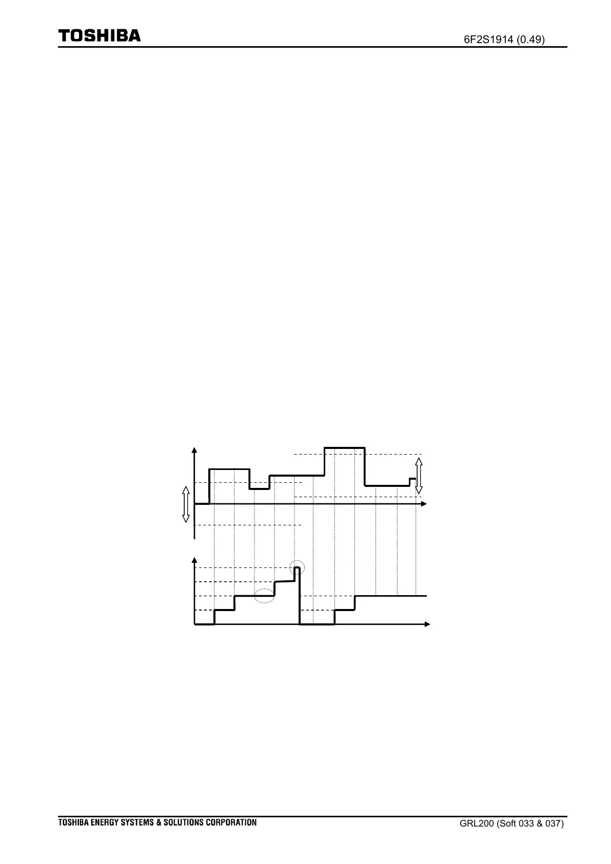
Figure 9.2-7 illustrates the operation for the SD feature about entering a current. At Time=0,
the current enters into the VCT and it is observed (Time=0). When the entering current is
being beyond the upper limit (Time=a), a repeated number is set for ‘1’. If the entering current
is out of the upper and lower limits (Time=b), the repeat number gets to have ‘2’. Note that the
repeated number is kept to have ‘2’ even if the entering current goes back within the upper
and lower limits (Time=c). The repeated number will be larger than the setting [Period SD]=3,
when the entering current is out of the upper and lower limits again (i.e., Time=d). Then, at
Time=e, the value of the entering current will be sent to the network, because the repeated
number is incremented. After that, the repeated number will be set zero (0); the new positon
for the SD feature is set (i.e., from Time=e).
First SD standardization level
Following SD position with [ISD]
First SD position with [ISD]
Figure 9.2-7 Dead band operation with [PeriodSD]=3
(ii) Check cycle in SD feature
The check cycle is defined for 500 milliseconds in the SD feature. (i.e., interval ab in Figure
9.2-7 is equal to 500ms). If the entering current, in Figure 9.2-7, is required to send promptly
when the entering current is beyond the limits, set 0 for the setting [Period SD].

 Loading...


