- 1453 -
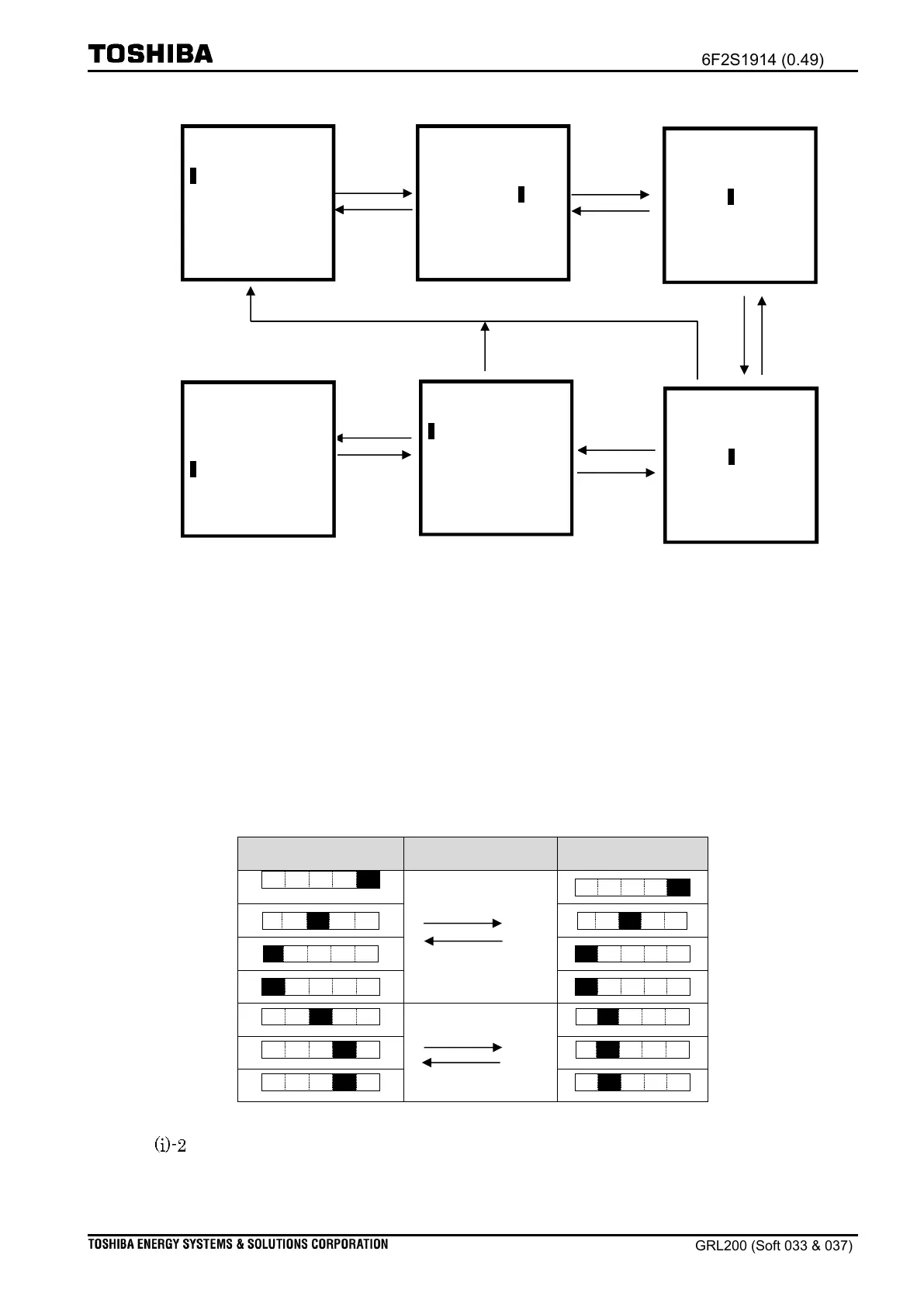
Figure 12.5-2 Steps for setting the value
1
Note: The meaning of settings and their setting process are beyond the scope of this
section. The figure above is provided by way of example. The user should confirm
the setting values after making any changes to their values. For verification, refer
to “Confirmation of Setting” discussed later.
2
Note: The operation keys have several features enabling the user to key values for
setting items. Table 12.5-1 shows values that have been changed before and after
the user presses the operation keys.
Table 12.5-1 Operation example when the operation keys are pressed.
Switch Setting Mode: The “Switch Setting Mode” is a setting used for the
selection of two modes. Figure 12.5-3 provides an example of the switch
setting mode. For each setting, the setting name and the selected item are
_OC1-b +
123.00000
OC1-c +
1.00000
OC1-angle +
45 deg
0
OC1-c +
1.00000
OC1-angle +
45 deg
3
.00000
OC1-c +
1.00000
OC1-angle +
45 deg
4
.00000
OC1-c +
1.00000
OC1-angle +
45 deg
*OC1-b +
124.00000
OC1-c +
1.00000
OC1-angle +
45 deg
*OC1-b +
124.00000
_OC1-c +
1.00000
OC1-angle +
45 deg

 Loading...


