- 707 -
(i) Receiving “change value for counter” from the remote end
Mapping of Input point required
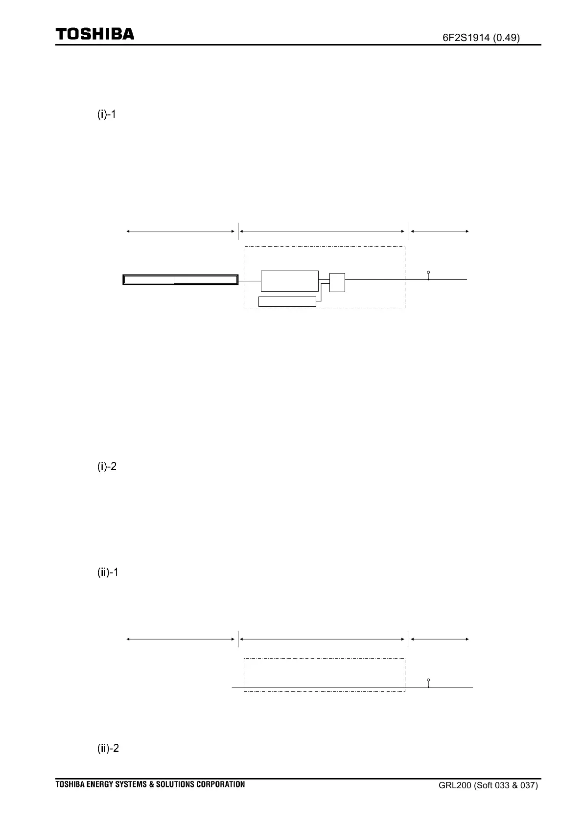
Figure 4.2-34 depicts the logic when a “change value for counter” command is received at the
DPSY01 logic. With regard to a three-phase counter, the input-point
“DEV01_3PH_CONTROL_REQ” is used. With regard to a phase-A counter, the input-point
“DEV01_APH_CONTROL_REQ” is used. For phase-B and phase-C, the input-points
“DEV01_BPH_CONTROL_REQ” and “DEV01_CPH_CONTROL_REQ” are used.
DPSY01 function (Function ID: 511001)
Command “change value for counter”
“DPSY01_SLD_CSCN”
(511001 8A02011F88)
Figure 4.2-34 Change counter value for three-phase
†
with operation from the remote-end in
DPSY01
‡Note: The “operate condition” signal is provided from the operate condition logic shown
in Figure 4.2-36.
†
Note: The user can apply other counter change commands for phase-A, -B, and –C as
shown in Table 4.2-24. The resultant signals for the DPSY02 logic are shown in
Table 4.2-25.
Output signal to BO
The DPSY01 function can issue a “Result” signal at output point “DPSY01_SLD_CSCN”. The
counter values are issued at points “DPSY01_CNT_VAL", “DPSY01A_CNT_VAL",
“DPSY01B_CNT_VAL", and “DPSY01C_CNT_VAL".
(ii) Receiving “change value for counter” from the local-end
Input signal from the front panel
Figure 4.2-35 depicts the logic when a “change value for counter” command is provided in the
DPSY01 function. The command is provided from the sub-menu (see Figure 4.2-33).
DPSY01 function (Function ID: 511001)
“DPSY01_SLD_CSCN”
(511001 8A02011F88)
Figure 4.2-35 Changing counter value by operation from the front panel in DPSY01
Output signal to BO

 Loading...


