- 757 -
Table 4.3-19 shows the required mapping signals in SOFTSW1 function to the IEC 61850
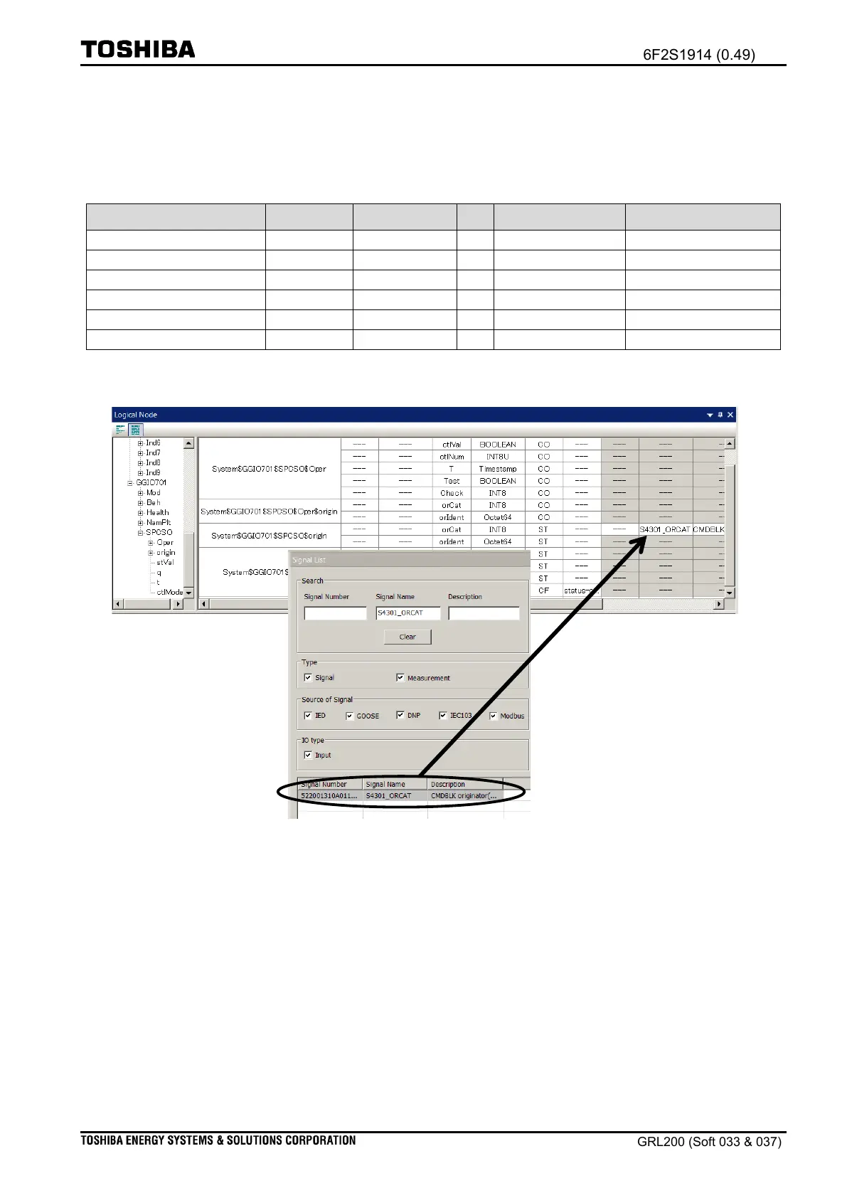
communications. Figure 4.3-25 shows how to map a signal.
Table 4.3-19 Mapping signals for SPCSO object.
Ctrl/GGIO701$SPCSO$origin
Ctrl/GGIO701$SPCSO$origin
Note: “Status (ST)” is defined in the function constraint (FC) of the IEC 61850 standard.
Figure 4.3-25 orCat attribute mapped into SPCSO object of GGIO701
(iii) Mapping input data
The SOFTSW1 function can receive three commands “select, operate, and cancel. Thus, the
user should map the input-point “S4301_CONTROL_REQ”. Table 4.3-20 shows the input-point
“S4301_CONTROL_REQ” and the Object reference “Ctrl/GGIO701$SPCSO”; the user should map
the Object reference having attributes CO and CF in FC† to the input-point. Figure 4.3-26 shows
how to map a signal.
†Note: The attribute is defined in the IEC 61850 standard; “CO” stands for “Control”
and “CF” stands for “Configuration” in the functional constraint (FC).

 Loading...


